Select: Difference between revisions
| Line 16: | Line 16: | ||
*[[Component segment|Select individual parts of a component]] | *[[Component segment|Select individual parts of a component]] | ||
*[[Mark#Signal|Signal segment|Mark single or multiple parts of signals]] | *[[Mark#Signal|Signal segment|Mark single or multiple parts of signals]] | ||
*[[Turn_/_rotate | *[[Turn_/_rotate|Programme mode for rotating marked elements]] | ||
*[[Displace_/_Move_/_Relocate_from|Programme mode for moving marked elements]] | *[[Displace_/_Move_/_Relocate_from|Programme mode for moving marked elements]] | ||
*[[Mirror|Mirror selected elements|Programme mode for mirroring selected elements]] | *[[Mirror|Mirror selected elements|Programme mode for mirroring selected elements]] | ||
Revision as of 09:32, 7 June 2021
Different methods for selecting
In order to provide one or more elements for future operations or actions, they must be selected or marked. This is usually done by clicking M1 on an element. To reach covered elements, hover the mouse pointer to the place of the element and press the keyboard key [s] (select) several times. If the desired object flashes, press [Return]. Now it appears selected/marked/highlighted. You can select signals, symbols and enclosures "always complete" or also individual parts of them. See below.
The following possibilities exist in principle:
- Left mouse button M1: Select by simply clicking on it.
- Right mouse button M2: Zoom in/context/rotate
- Select individual, also hidden elements
- Programme mode for marking elements
- Capture Window or Capture polygonal: Select several elements at the same time
- Menu item to select all parts of the circuit
- Menu item to deselect all parts of the circuit
- Menu item to deselect all selected parts of the circuit and vice versa
- Select individual parts of a component
- Signal segment|Mark single or multiple parts of signals
- Programme mode for rotating marked elements
- Programme mode for moving marked elements
- Mirror selected elements|Programme mode for mirroring selected elements
- If you want to select only certain characteristic values within an element group, e.g. among all vias only those with drill hole diameter 0.8mm -- see below
Select elements
You can reach this mode...
by [s] or
by "Select" in menu "Edit" or
by the tool ![]()
Leave this mode...
by [ESC] or M12
You can select elements, signals or components for further actions. They are highlighted optically. If you want to change for instance the width of a signal segment, hover the cursor over it and choose the "select" command. The status bar shows: Choose elements. The advantage of the select command compared to just clicking M1 onto an element is, that you have a tool like a scalpel to exactly select single elements even in regions where there are many elements on top of each other on different layers or if you have a zoom step, with few details.
If you have highlighted an element, you can add another element to your selection by adding the [Shift] key.
If you have chosen a component and want to add another component to your selection, please use the [Ctrl] key.
You can also use the [Maj] and/or [Ctrl] keys together with M11 to select the second, third and 4th best element. Also the "Selection Assistant" in menu "Edit" can help: Select all vias with a certain height and with.
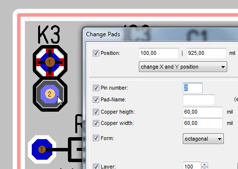
Note: Press "s" for select several times then press "e" for edit
 | then |  |
If several elements are placed superposed to each other, e.g. Pad number 1 and the handle cross it is difficult to touch them individually. Now use keyboard key [s]. Place the cursor upon the element you like to highlight and press keyboard key [s] as long as the element you like to highlight flashes. Press [Enter] to highlight it. Now press keyboard key [e] in order to open the corresponding dialog for edition. Using key [-] allows stepping back if you had pressed [e] too often. Key [+] allows stepping ahead.
Select single elements or single segments
In order to select only one segment of a track or only a single element of a component, click M2 on empty space. A context menu will open. Untick the first option: "Always select entire component". Within the same context menu please find the entry: "Select signal...". Here you can determine, whether a M1 click highlights a segment of the signal, a branch of the signal, the signal island or the complete signal.
In the sidebar from the first row left select the function for selection of signal segments (button background grey = activated). In order to highlight elements of a drawing separately, the second button in the second row mustn't be highlighted (button background black = deactivated).

(Image: Sidebar setting to highlight only segments)
Add to selection
Select additional elements
If you want to add further elements to a selected element, press the [Ctrl] or [Shift] key while clicking further elements. It is like Windows: Using [Shift] highlights all inbetween two clicks, using [Ctrl] highlights just the clicked ones.
Select a polyline or strand
If you want to select a contiguous polyline (e.g. a strand of track), first select only the first segment. Hold the [Shift] or [Shift]' key while clicking on the last segment of the chain. All segments between the first and the last are now also marked. However, this only works for a linear string. There mustn't be a connection, soldering point or T-piece in between.
Select further sections of the signal (More & More)
If you repeatedly click on a signal (schematic or layout) at the same place (in the picture on the left), successive signal segments are marked in addition, according to the buttons in the sidebar:
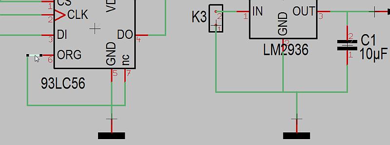
Image: First click highlights signal segment: ![]()

Image: Second click highlights signal branch: ![]()
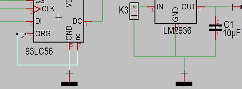
Image: Third click highlights signal island (= all segments connected): ![]()

Image: Forth click highlights the whole signal (= including sinal segments on other locations and/or power/supply connections: ![]()
Enlarge selection by [Shift] and [M1]
Image: The left track segment was selected with [M1], the right track segment is clicked with [Shift] + [M1]. In between are 2 Dukos and a T-junction.
With the combination [Shift] + [M1] it is possible to highlight a string of a signal in the layout, even through vias and despite T-junctions.
Find and select
This function is used to locate components and signals in the schematic- and PCB-view. The according elements will be highlighted and the active window will be scaled for best view. Press also key [f] for find. The following dialog appears:
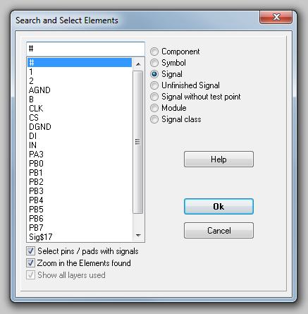
All signals can be listed, which are not completely routed. Selecting the function Zoom found elements in the center places the elements to be searched centered on the screen. The according schematic page will be displayed in schematic mode. Is a signal or component located on several pages, TARGET 3001! will display special note.
Select all
Select is used to mark and highlight all elements.
Deselect all
All elements will be unselected by clicking into empty space or by [Shift]+[Esc] or by menu Edit/Deselect all...
Invert selection
All selected elements will be unselected, all visible but not selected elements will be selected. If you have moved the layout outside the limited area of 2m x 2m, it is usually not possible to catch the layout completely, because of the limitation of the active mouse area. Please click now M1 on a free spot outside the layout area, to make sure that no element has been selected and use the Invert Selection function. Now everything is highlighted and can be moved.
Selection assistant
Your problem: you have large number of octagonal pads with a diameter of 55.12 mil and another large number of octagonal pads with a diameter of different mil in your layout. Now you wish to widen the 55.12 pads to 60mil. The selection assistant gives you the opportunity to highlight those drillholes among all drillholes which have the property of 55.12mil diameter. Priority is not making the selections visible on screen but generating a "partly selection" and a "partly additive selection" of elements to set properties by using the dialog "Edit the selected elements" by pressing keyboard key [e].
The Selection Assistant is located in menu "Edit":
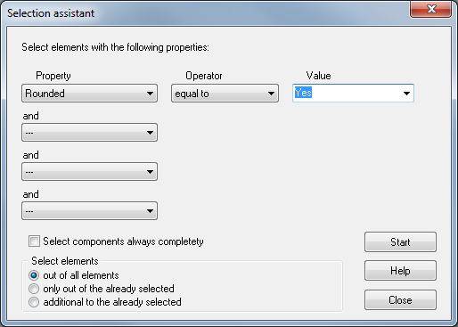
You can highlight several elements or properties of specific elements selectively to make individual settings. In those pull-down menus operators, properties and values/units project related can be chosen. In the example project pic.t3001we want to highlight all those soldering pads showing a octagonal pad with height and width of 55.12 mil. We intend to change the measurements. First we enter those properties and values of those elements we wish to select:
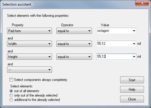
After pressing button "START" a message appears, showing the number of highlighted elements. Confirming this dialog it remains on screen for to additively select further elements or properties or values without loosing the already done selection. This allows eventually "or"- operations. If you close the selection assistant, the following picture shows:
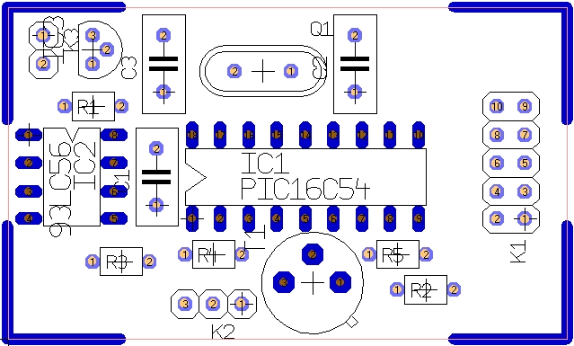
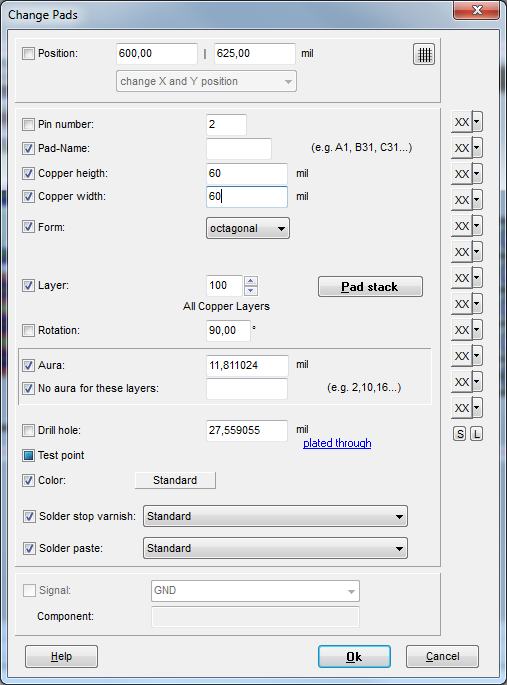
Now press key [e] for "Edit" and enter to the following dialog:
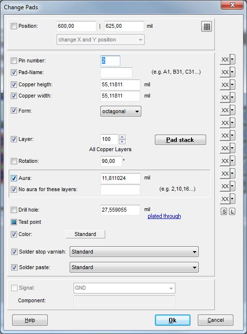
Change the pad height and width from 55.12mil to 60mil.
The result is immediately to be seen.
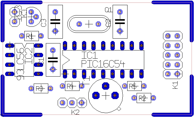
Check it by doubleclicking the changed element:
