Track width: Difference between revisions
No edit summary |
No edit summary |
||
| Line 1: | Line 1: | ||
The width of a track to be placed (a future track) can be set '''during track placement''' by pressing the keyboard key [O] for | = Define the entire track width for a signal in the schematic already = | ||
If you want to define the track width for an entire signal (net) beforehand, double-click a green signal segment of this signal ([[M11]]) in the '''schematic''. In the dialog "Change signal wires" you can define the minimum track width and the minimum track spacing at "Signal". If you now want to place a track in the layout, it immediately has the required minimum width. This value also will be used by an autorouter. | |||
= Define track width for coming tracks in the layout = | |||
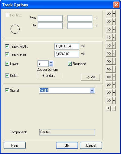
The width of a track to be placed (a future track) can be set '''during track placement''' by pressing the keyboard key [O] for <u>o</u>ptions. So start a track by pressing keyboard key '''[2]''' or by the use of the [[Image:DrawTrack.jpg]] Draw Track icon. Now you're in the "Place tracks" mode. Now press key [O]. The following dialog opens: | |||
Revision as of 16:11, 15 March 2018
Define the entire track width for a signal in the schematic already
If you want to define the track width for an entire signal (net) beforehand, double-click a green signal segment of this signal (M11) in the 'schematic. In the dialog "Change signal wires" you can define the minimum track width and the minimum track spacing at "Signal". If you now want to place a track in the layout, it immediately has the required minimum width. This value also will be used by an autorouter.
Define track width for coming tracks in the layout
The width of a track to be placed (a future track) can be set during track placement by pressing the keyboard key [O] for options. So start a track by pressing keyboard key [2] or by the use of the ![]() Draw Track icon. Now you're in the "Place tracks" mode. Now press key [O]. The following dialog opens:
Draw Track icon. Now you're in the "Place tracks" mode. Now press key [O]. The following dialog opens:
The width of already existing signal tracks can be changed with the keyboard key [@] or [e] for editing. The desired tracks must be selected before executing the edit command. To decide which part of the track you wish to select, please use these icons:
![]() ... the selection of that single segment.
... the selection of that single segment.
![]() ... the selection of a branch of the signal.
... the selection of a branch of the signal.
![]() ... the selection of the connected signal island.
... the selection of the connected signal island.
![]() ... the selection of the whole signal in that view.
... the selection of the whole signal in that view.
Now enter to the dialog "Change Tracks". A Doubleclick M11 will do the same. Shall the track width be defined in advance for a whole signal (net), you can double click a green signal segment in the schematic with M11. In the appearing dialog "Change signal wires" you can set the minimum track width and the minimum spacing for the whole signal. If you now start a track in PCB, the desired track width is used automatically.
So the Options-dialog cares for the properties of future tracks, the Change-dialog modifies already existing tracks. This rule applies for all drawing elements in TARGET 3001!.
Keywords: Track, Width, Trace, Thickness, Strength, Weight


