Measure
General
You can reach this mode...
by key [u],
by "Measure and dimensioning" in Menu Actions
or by the tool ![]() under the icon
under the icon ![]()
Leave this mode...
with [ESC] or M12
For a quick information the little info box might be sufficient. It is fixed to the cursor as soon as you press the [u]-key for measuring:
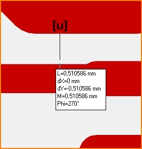
Image: Infobox at "measure". The mouse pointer was moved after pressing the [u] key from the red border in the north over the white to the south to the opposite red border. The black line shows the distance.
It means: L=Length of the air wire of the measurement, M=Manhattan Metric= dY+dX, Phi=Angle measured from the starting point of the measurement, started at 15:00 (= 0°) counterclockwise.
Measure and dimensioning
The status line shows the x- and y-portions of the distance (dx and dy), the distance itself (L) and the Manhattan-length (M=dx+dy). When drawing tracks also see the signal length (S). You might switch off the grid for a short time with [F6] to measure very exactly.
Add a dimensioning by pressing...
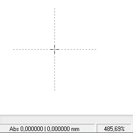
...[u] at the starting point
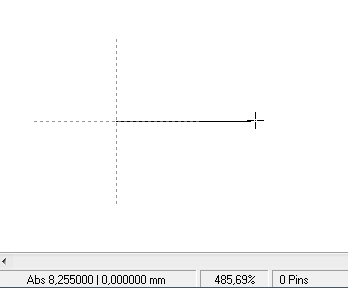
...and a mouseclick M1 at the end of a distance.
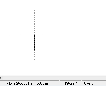
Now hover the mouse orthogonally to open area and click again.
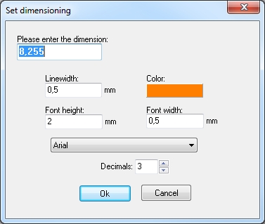
Confirm the opening dialog...
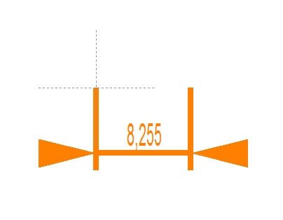
...and see the digits of the dimensioning on your layout or schematic.
Edit the digits like normal text (doubleclick on it or single click and [e] for edit, then follow the dialog).
Entering non measure values
If you enter a different value to the measure dialog box than the one given, e.g. 4.00m instead of 8.255mm, the value is marked by an underscore. This is to indicate that the figure shown is not the one measured by scale but a different figure, entered following the idea of the layouter.
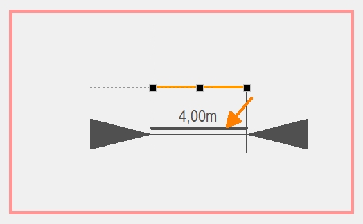
Image: The value entered does not represent the real length of the line but a individual value chosen by the designer. indicated by underscore.
Finding coordinates that are not on the grid
To be able to measure things that are not on the grid, use the [+] key to find these points. Look here.
Dimensioning the drills of the complete layout
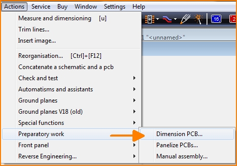
Find it in menu "Actions" on the bottom of the list.
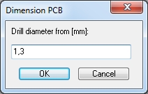
First you get asked from which diameter the dimensioning shall be displayed. Here we want to have all dimensions from drills bigger than 1.3 mm (included)
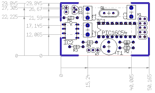
That is how it comes out. The digits can be edited like any text.
Dimensioning using a snap point
Use the function "Measure and dimensioning" from menu "Actions". In the status bar you can read "Measure from...". Hover the mouse close to the starting point but you don't click. Instead you press keyboard key [+] Now you can choose from significant points nearby by the use of the keyboard keys "up" and "down" in order to determine the desired snap point. The cursor follows. Press key "Return" for OK.
In respect to the target coordinate you do exactly the same: move the mouse close to the measuring target. No click! Press key [+], select the point of interest using the arrow keys and press [Return]. Now you only need to decide where to put the measuring arrow (an element of technical drawing). Done.
Dimensioning angles and radii
As of V33, you can also dimension angles and radii very easily:
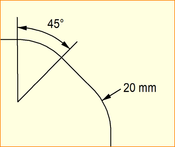
Image: Dimensioning angles and radii
For an angle, use the menu item "Actions / Angle dimensioning". First click on the center point with M1 and define the first leg and then the angle and the arc line with the arrows. You can determine whether the angle is displayed in a clockwise direction by the direction in which you sweep over the start leg.
You can then define the shape of the label in the dialog that opens.
To dimension a radius, please select an arc (torus). Three small black boxes will appear. In the context menu (M2) of the black boxes, select the "Dimension radius / diameter" item and use M1 to define the direction and length of the arrow. A diameter symbol also appears next to the text in the dialog for full circles. Otherwise, the radius is displayed.

