Créer le fichier de placement automatique (pick&place) : Différence entre versions
| Ligne 2 : | Ligne 2 : | ||
| − | [[Image:f_placAutoDlg.jpg|Le dialogue Pick & Place dans menu [[menu Fichier|Fichier]] / [[Import-Export de fichiers de FAO|Utilitaires: Import-Export de fichiers FAO]] / [[Production | Production]]]]Le dialogue Pick & Place dans menu [[menu Fichier|Fichier]] / [[Import-Export de fichiers de FAO|Utilitaires: Import-Export de fichiers FAO]] / [[Production | Production]] | + | [[Image:f_placAutoDlg.jpg|Le dialogue Pick & Place dans menu [[menu Fichier|Fichier]] / [[Import-Export de fichiers de FAO|Utilitaires: Import-Export de fichiers FAO]] / [[Production | Production]]]]Le dialogue Pick & Place dans menu [[menu Fichier|Fichier]] / [[Import-Export de fichiers de FAO|Utilitaires: Import-Export de fichiers FAO]] / [[Production | Production]]<br> Ici vous pouvez entrer les informations relatives au [[placement automatique]] (pick and place) dans un fichier. |
| − | |||
| − | |||
| − | Ici vous pouvez entrer les informations relatives au [[placement automatique]] (pick and place) dans un fichier. | ||
TARGET utilise le <b>centre</b> de chaque composant. Donc TARGET dessine un <b>rectangle autour les centres des pastilles</b> de composant. Le centre de ce rectangle produit les coordonnées de composant. Les composants très asymétriques peuvent produire des coordonnées qui demandent un offset dans la configuration du machine concernant ces composants. | TARGET utilise le <b>centre</b> de chaque composant. Donc TARGET dessine un <b>rectangle autour les centres des pastilles</b> de composant. Le centre de ce rectangle produit les coordonnées de composant. Les composants très asymétriques peuvent produire des coordonnées qui demandent un offset dans la configuration du machine concernant ces composants. | ||
| − | |||
| − | |||
| − | |||
| − | |||
This dialog allows the creation of data on automatic "picking and placing" into a '''text file'''. Coordinates are relative to the lower '''left''' corner of the PCB. If you however select "Only components on bottom", then the lower '''right''' corner is the origin. This is because you should insert the PCB bottom side top into your machine.<br><br> | This dialog allows the creation of data on automatic "picking and placing" into a '''text file'''. Coordinates are relative to the lower '''left''' corner of the PCB. If you however select "Only components on bottom", then the lower '''right''' corner is the origin. This is because you should insert the PCB bottom side top into your machine.<br><br> | ||
TARGET 3001! uses the coordinates of the <b>center</b> of each component being derived from the complete footprint image-outline. | TARGET 3001! uses the coordinates of the <b>center</b> of each component being derived from the complete footprint image-outline. | ||
| − | |||
Version du 15 juillet 2014 à 16:37
Vous trouvez ces informations dans le menu Fichier / Utilitaires: Import-Export de fichiers FAO / Production
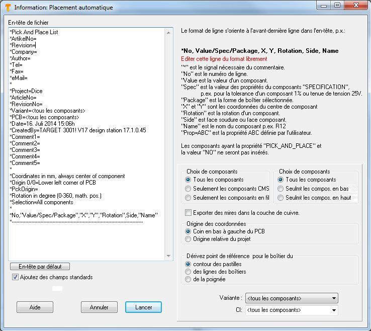
 Le dialogue Pick & Place dans menu Fichier / Utilitaires: Import-Export de fichiers FAO / Production
Ici vous pouvez entrer les informations relatives au placement automatique (pick and place) dans un fichier.
TARGET utilise le centre de chaque composant. Donc TARGET dessine un rectangle autour les centres des pastilles de composant. Le centre de ce rectangle produit les coordonnées de composant. Les composants très asymétriques peuvent produire des coordonnées qui demandent un offset dans la configuration du machine concernant ces composants.
This dialog allows the creation of data on automatic "picking and placing" into a text file. Coordinates are relative to the lower left corner of the PCB. If you however select "Only components on bottom", then the lower right corner is the origin. This is because you should insert the PCB bottom side top into your machine.
TARGET 3001! uses the coordinates of the center of each component being derived from the complete footprint image-outline.
User defined property
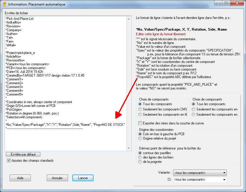
Maybe you'd like to put out a certain property of the components to the pic & place list, for example the stock number. Precondition is, that the components in question show this property and a value to this property is given. So add to the last but one line: ,"Prop=STOCKNUMBER"- important is the comma and the quotation marks. In the layout you for example have 5 components in use, furnished with individual stoch mumbers:
In the Pic&Place dialog it looks like that:
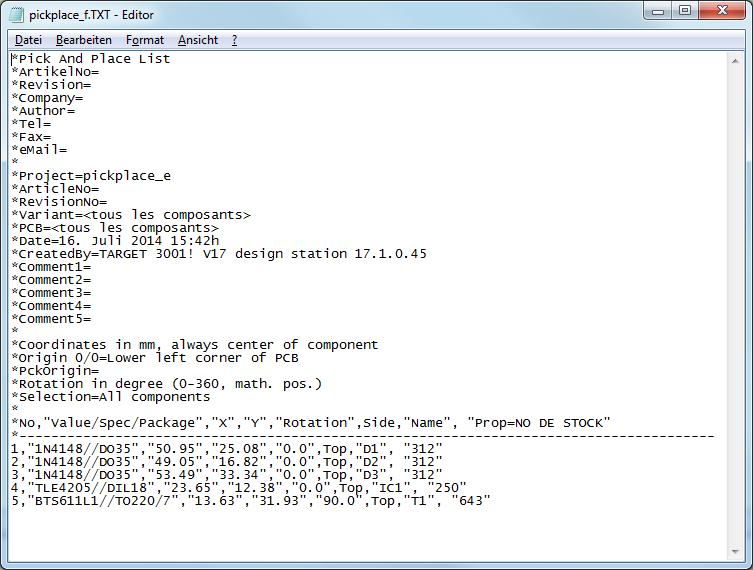
If you push the start button, the following entries are visible:

Image: The Pic&Place result
It is a simple text file, to be edited by any text editor. The desired STOCKNUMBERS see in the last column..
fr:Créer le fichier de placement automatique (pick&place)


