Générateur de boîtier
Le dialogue "Générateur de boîtier"
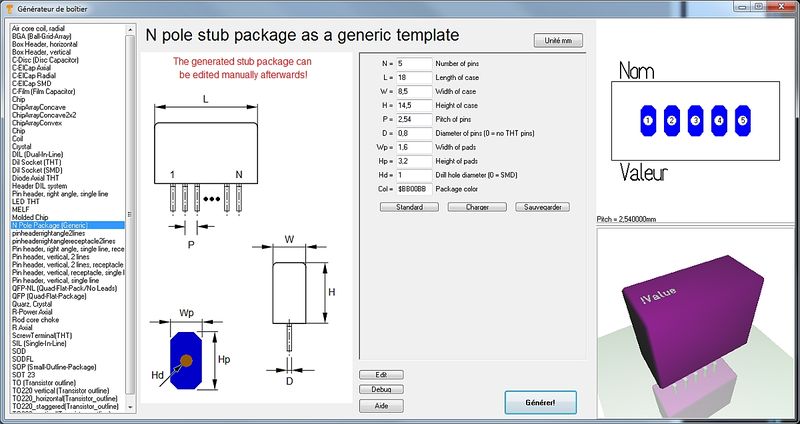
Le "Générateur de boîtier" est destiné pour la création facile de boîtiers de composants et la vue 3D. Il se trouve dans le menu "Boîtiers" en vue PCB et s'ouvre comme ça:
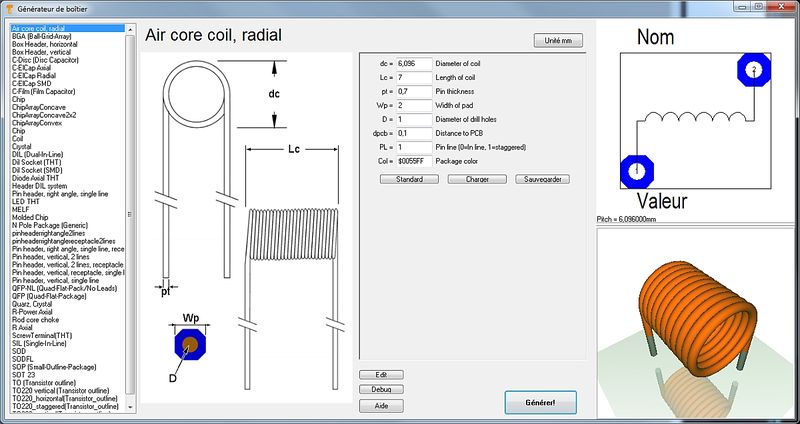
Image: Le dialogue "Générateur de boîtiers"
Il se compose de trois parties: un dessin technique à gauche, contenant la définition des paramètres du boîtier. Tel dessin peut être trouvé dans quelconque fichier technique. Cet image ne peut être modifié ici. Moyen de la boîte de dialogue, vous trouverez la liste des paramètres, où tous les paramètres peuvent être saisis selon les spécifications de la fichier technique. Il est la base de la façon dont le boîtier plus tard va ressembler. Les abréviations gauche du signe égal sont les mêmes que dans le dessin technique à gauche. À droite de l'image on regarde le boîtier le même comme dans le pcb plus tard. Ci-dessous l'image 3D apparaît.
Le type de composant pour création peut être sélectionné dans la liste en haut à gauche:
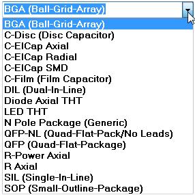
Image: La liste de types de composants
Si vous selectionnez un boîtier DIL (Dual-In-Line) de la liste, l'image de dialogue s'echange pour entrer les paramétres spécifiques pour composants DIL.
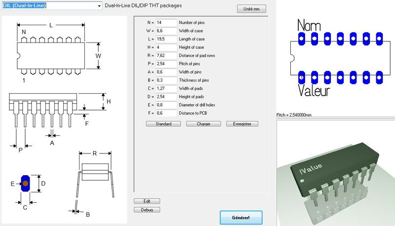
Image: Le dialogue pour un DIL
Le bouton Unité mm (en haut au centre) tient à préciser que l'échelle métrique a prévalu contre pouces dans le dessin des composants. Il n'ya pas de pouces-échelle ici.
Les boutons Standard, Charger, Sauvegarder dans le centre du dialogue se référer à l'ensemble des valeurs actuellement inscrits. On peut sauvegarder certains ensembles de valeurs sous un nom individuellement et les charger encore. Ou on peut utiliser l'ensemble "Standard".
Le bouton Générer! ouvre la boîte de dialogue bien connu pour sauvegarder le boîtier à la base de données. Type de composant, le nom du composant, la description du boîtier et le fabricant peuvent être saisis comme d'habitude et le processus est terminé. En ce qui concerne les boutons Modifier et Debug s'il vous plaît voir les chapitres ci-dessous.
Quick creation of a package using the N-Pole type
Si vous n'êtes pas un programmeur et vous n'aimez pas à créer un script pour un un boîtier qui n'est pas représentée ici, vous pouvez utiliser le type N-Pole. Trouvez cet option dans la liste:
L'idée est simplement d'avoir un aperçu de boîtier avec un certain type et nombre de pastilles dans une rangée. Ainsi, il est le fait que le paquet ne viens pas parfaitement du générateur, mais le générateur lui-même a déjà fait beaucoup de travail constructif. Vous pouvez importer ce "flan" à une mise en page de PCB, faire des corrections, pousser des pastilles sur leur location correcte et sauvegarder le boîtier encore sous la même nom. Bien sûr, vous savez que dans la mise en page de PCB, vous pouvez modifier le boîtier à tout moment et le sauvegarder à nouveau (l'écraser ou le sauvegarder sous un nom différent).
How to create a package script
What is a package script?
Each component type which you will find in the list top left is based on exactly one script. So what you see in the dialog window when selecting a certain component type is defined by a script. A package script is a program which determines the geometrical shape of all drawing elements of a package. It is called script because it is stored as a text. So one does not create a script for one singular more or less complicated package but always for a package kind or type. A package type normally is built up according to special geometrical rules, only the number of leads (this is the easiest case) varies. View the script of package type by pressing the button: ![]()
You can modify each script, save it under a different name ("Save as...") and then use it. When opening the package generator dialog again, the new script can be chosen from the list.
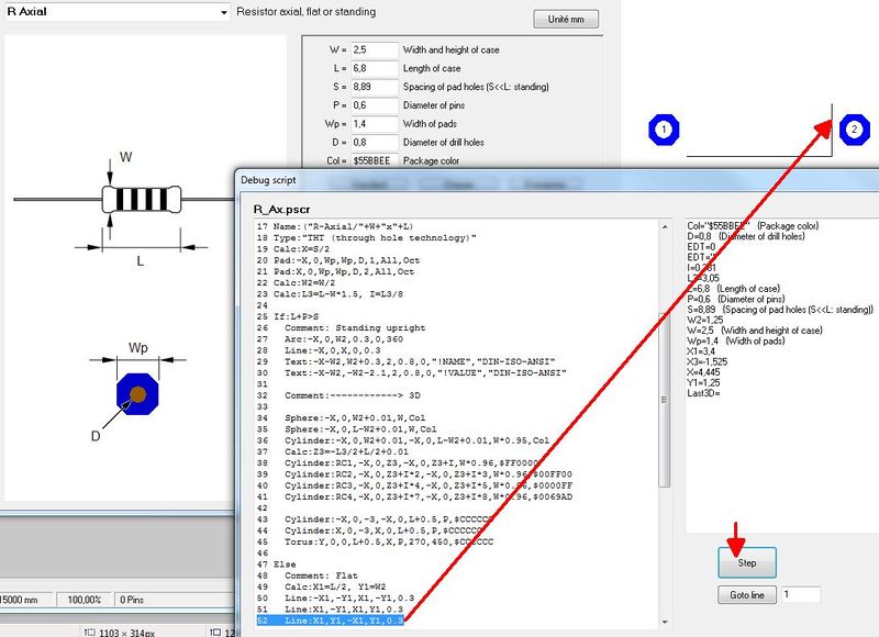
Button: ![]() opens the "Debugger" of the script.
opens the "Debugger" of the script.
The "Step" button in the debug dialog allows a step by step (= row by row) walk through the script in order to see what each script row effects for the image(s). So if bugs in the script would occur, one can easily find them and fix them. In the above dialog for example row 52 is responsible for the vertical line on the right edge of the package outline.
The setup of a script by an example
For the component type SIL (Single-In-Line) the script has the following look (syntax to the left, explanation to the right):
| Script syntax (line by line) | Explanation |
|---|---|
| 01 Script:"SIL (Single-In-Line)" | Name of the script, shown in the selection box top left. Active with the next opening of the generator. |
| 02 Hint:"Single-In-Line SIL/SIP THT packages" | Hint which appears in the dialog right beside the selection box. |
| 03 Comment:"TARGET 3001! package script, Unit mm" | All following in this line is comment. |
| 04 Author:"Steve Miller" | Author of the script. |
| 05 Date:"28.11.2013" | Date of last modification. Needs to be controled/managed manually. |
| 06 Image:"SIL.png" | File name of the image shown to the left. PNG-Image always 350x580 pixel. |
| 07 Num:N,7,"Number of pins",Edt | Declare numeric variable. Here the input box "Number of pins" is defined. Name, Default value, Hint, Display. Display missing=not shown, EDT=editable, RDO=Read-Only. Variable names need to start with one or more alphabetic character. Then numeric characters may follow. Upper case/lower case is not recignized. |
| 08 Num:W,2.5,"Width of case",Edt | dito. Input box "Width of case" is defined. |
| 09 Num:L,18,"Length of case",Edt | dito. Input box "Length of case" is defined. |
| 10 Num:H,5.1,"Height of case",Edt | dito. Input box "Height of case" is defined. |
| 11 Num:P,2.54,"Pitch of pins",Edt | dito. Input box "Pitch of pins" is defined. |
| 12 Num:A,0.6,"Width or radius of pins",Edt | dito. Input box "Width or radius of pins" is defined. |
| 13 Num:B,0.3,"Thickness of pins or zero",Edt | dito. Input box "Thickness of pins or zero" is defined. |
| 14 Num:C,1.5,"Width of pads",Edt | dito. Input box "Width of pads" is defined. |
| 15 Num:D,2.5,"Height of pads",Edt | dito. Input box "Height of pads" is defined. |
| 16 Num:E,0.9,"Diameter of drill holes",Edt | dito. Input box "Diameter of drill holes" is defined. |
| 17 Num:F,0.1,"Distance to PCB",Edt | dito. Input box "Distance to PCB" is defined. |
| 18 Str:Col,"$225522","Package color",Edt | Declare text variable. Name, Default value, Hint, Display. Display missing=not shown, EDT=editable, RDO=Read-Only. Colors need to be defined hexadecimally like $BBGGRR . The two B represent Blue, the two G represent Green and the two R represent Red. |
| 19 |
Blank line |
| 20 Comment:------------> Drawing |
Comment: The syntax of the package (land pattern with package outline) starts from here. |
| 21 |
Blank line |
| 22 Name:("SIL-"+N+"/"+L+"x"+W+"x"+H) |
This is how the proposal for a package name is created when pushing the "Generate" button. It is a string. The visible is denoted within quotes. Those characters added by a plus sign are variables. |
| 23 Type:"SIL / SIP (single in-line package)" |
Package type. Please inherit from data base "package types". |
| 24 Calc:X1=(N/2-0.5)*P |
Announce a calculation. Variable=Expression. More than on calculation separate by comma. Operators within the expression: +, -, *, /, (), mathematic functions, see below. |
| 25 For:I,1,N |
Begin a For-loop. Hereby iteratively is executed what line 26 defines: Variable name, Start value, End value, (step=1). Start value and End value can be expressions. |
| 26 Pad:-X1+P*(I-1),0,C,D,E,I,All,Oct |
Create a pad in the layout. X, Y, Width, Height, Drill diameter, Layer, Form, Rotation, (Padname=), (Solder paste=True), (Solder stop=True). |
| 27 EndFor |
Ende of the For loop. For loops can be nested. Colon optionally. |
| 28 Calc:X=L/2 |
Announce a calculation. Variable=Expression. More than on calculation separate by comma. Operators within the expression: +, -, *, /, (), mathematic functions, see below. |
| 29 Calc:Y=W/2 |
Announce a calculation. Variable=Expression. More than on calculation separate by comma. Operators within the expression: +, -, *, /, (), mathematic functions, see below. |
| 30 Line:-X,-Y,X,-Y,0.3 |
Draw a line in the layout. X1, Y1, X2, Y2, (Line width=0.3), (Layer Function=4=Position top).
|
| 31 Line:X,-Y,X,Y,0.3 |
Draw a line in the layout. X1, Y1, X2, Y2, (Line width=0.3), (Layer Function=4=Position top).
|
| 32 Line:X,Y,-X,Y,0.3 |
Draw a line in the layout. X1, Y1, X2, Y2, (Line width=0.3), (Layer Function=4=Position top).
|
| 33 Line:-X,Y,-X,-Y,0.3 |
Draw a line in the layout. X1, Y1, X2, Y2, (Line width=0.3), (Layer Function=4=Position top).
|
| 34 Calc:X=X1-P/2 |
Announce a calculation. Variable=Expression. More than on calculation separate by comma. Operators within the expression: +, -, *, /, (), mathematic functions, see below. |
| 35 Line:-X,Y,-X,-Y,0.3 |
Draw a line in the layout. X1, Y1, X2, Y2, (Line width=0.3), (Layer Function=4=Position top).
|
| 36 Text:-X+1.5,W/2+1,2.5,1.6,0,"!Name","DIN-ISO-ANSI" |
Display text in the layout. X, Y, Hight, Width, Rotation, Text content, Charcter set, (Layer function=4=Position top). |
| 37 Text:-X+1.5,-W/2-3.2,2.5,1.6,0,"!Value","DIN-ISO-ANSI" |
Display text in the layout. X, Y, Hight, Width, Rotation, Text content, Charcter set, (Layer function=4=Position top). |
| 38 Comment:------------> 3D |
Comment: The syntax of the 3D image starts from here. |
| 39 Solid:0,0,F,0,0,F+H,L,W,Col,0.4 |
Display a cuboid in 3D. X1, Y1, Z1, X2, Y2, Z2, Width, Height, Color, (Champfer radius=0). The Syntax for the 3D modelling applies. |
| 40 Text3D:-X1+1.5,-0.5,F+H+0.01,1.2,0.5,0,"DIN-ISO-ANSI","!Value",$FFFFFF |
Display text in the 3D image. X1, Y1, Z1, Height, Width, Rotation, Character set, Text content, Color. The Syntax for the 3D modelling applies. |
| 41 Cylinder:-X1,0,F+H-0.1,-X1,0,F+H+0.01,1,$FFFFFF |
Display cylinder in 3D. X1, Y1, Z1, X2, Y2, Z2, Diameter, Color, (Champfer radius=0). The Syntax for the 3D modelling applies. |
| 42 For:I,1,N |
For loop in order to create the 3D leads iteratively |
| 43 Calc:X2=-X1+P*(I-1),Y2=0,Z=(F+H)/2 |
Announcement of a calculation |
| 44 IF:B>0 |
Start If condition. Expression Operator Expression. Operators: =, <, >, <=, >=. Combine several conditions by & (=and). |
| 45 Solid:X2,Y2,-3,X2,Y2,0.1,A,B,$CCCCCC,0 |
Display a cuboid in 3D. X1, Y1, Z1, X2, Y2, Z2, Width, Height, Color, (Champfer radius=0). The Syntax for the 3D modelling applies. |
| 46 ELSE |
Else branch. Colon optional. |
| 47 Cylinder:X2,Y2,-3,X2,Y2,0.1,A,$CCCCCC |
Display cylinder in 3D. X1, Y1, Z1, X2, Y2, Z2, Diameter, Color, (Champfer radius=0). The Syntax for the 3D modelling applies. |
| 48 ENDIF |
End of the If condition. If conditions can be nested. Colon optional. |
| 49 EndFor | End of the For loop. For loops can be nested as well. Colon optional. |
Please note: The values of the variables for the current SIL package are denoted on the right hand side of the debugger dialog.
Script commands
General
Every textual indication (=string) is embedded in quotes. Example: "Hello".
Coordinate indications are in metric scale [mm]. If you look on the X-Y-plane, the positive Z-axis points upward to the spectator.
Numeric characters are rounded to 1/1000.
Angle indications are in 0...360 degrees [°].
The rotational direction is CCW (=CounterClockWise). 0° is east.
The right-hand-rule applies for all axes.
Colors are indicated hexadecimally according to $BBGGRR. B represents Blue, G represents Green and R represents Red.
Script commands in detail
The following script commands currently exist:
- SCRIPT: Name of the script, shown in the selection box top left. Active with the next opening of the generator.
- HINT: Hint which appears in the dialog right beside the selection box.
- COMMENT: All following in this line is comment.
- AUTHOR: Author of the script.
- DATE: Date of last modification. Needs to be controled/managed manually.
- IMAGE: File name of the image shown to the left. PNG-Image always 350x580 pixel.
- TYPE: Package type. Please inherit from data base "package types".
- NAME: This is how the proposal for a package name is created when pushing the "Generate" button. It is a string. The visible is denoted within quotes. Those characters added by a plus sign are variables.
- NUM: Declare numeric variable. Here the input box "Number of pins" is defined. Name, Default value, Hint, Display. Display missing=not shown, EDT=editable, RDO=Read-Only. Variable names need to start with one or more alphabetic character. Then numeric characters may follow. Upper case/lower case is not recognized.
- STR: Declare text variable. Name, Default value, Hint, Display. Display missing=not shown, EDT=editable, RDO=Read-Only.
- CALC: Announce a calculation. Variable=Expression. More than on calculation separate by comma. Operators within the expression: +, -, *, /, (), mathematic functions:
- ABS(x) Absolute,
- SIN(x) Sinus [°],
- ASIN(x) Arcus Sinus,
- COS(x) Cosinus,
- ACOS(x) Arcus Cosinus,
- TAN(x) Tangens,
- ATAN(x) Arcus Tangens,
- MAX(x,y) Major value of the expressions x and y,
- MIN(x,y) Minor value of the eypressions x and y,
- INT(x) Integer, rounded,
- SQR(x) Square,
- SQRT(x) Square root,
- EVEN(x) 1 if even, 0 if uneven,
- ODD(x) 1 if uneven, 0 if even.
- Calculations for strings only know the operator + for appending and the following functions:
- NCH(i) Number-Character: 1=A, 2=B, ... 21=Z, 22=AA, 23=AB, ... 42=AZ, 43=BA ... (e.g. for the line namings of BGA packages)
- CHR(i) ASCII-Characters: 33=!, ... 65=A, 66=B, ... 90=Z, ... 97=a, 98=b, ... 122=z, ... 219=?
- INT(i) Integer, rounded,
- REAL(i) Decimal character with 3 digits after the decimal point
- FOR: Begin a For loop. Hereby iteratively is executed what line 26 defines: Variable name, Start value, End value, (step=1). Start value and End value can be expressions.
- ENDFOR:End of the For loop. For loops can be nested. Colon optionally.
- IF: Start If condition. Expression Operator Expression. Operators: =, <, >, <=, >=. Combine several conditions by & (=and).
- ELSE: Else branch. Colon optional.
- ENDIF: End of the If condition. If conditions can be nested. Colon optional.
- PAD: Create a Pad in the layout view. X, Y, Width, Height, Drill diameter, Layer, Form, Rotation, (Padname=), (Solderpaste=True), (Solderstopp=True).
- Layer = Top or Bot or All
- Form = Rnd or Oct or Rct or Ovl
- Solder paste = True or False
- Solder stopp = True or False
- Specifications in brackets are optional. Default is going to be used.
- LINE: Draw a line in the layout. X1, Y1, X2, Y2, (Line width=0.3), (Layer Function=4=Position top).
- Layer function: 3=Position bottom, 4=Position top, 12=Solder stop top, 15=Solder paste top, 16=Gold top, 18=Glue top
- ARC: Draw an arc in the layout. X, Y, Radius, Line width, Start angle, End angle, (Layer function=4=Position top).
- CIRC: Draw a circle in the layout. X, Y, Radius, (Layer function=4=Position top).
- TRI: Draw a triangle in the layout. X1, Y1, X2, Y2, X3, Y3, (Layer function=4=Position top).
- RECT: Draw a rectangle in the layout. X, Y, Width, Height, Rotation, (Layer function=4=Position top).
- TEXT: Display text in the layout. X, Y, Hight, Width, Rotation, Text content, Character set, (Layer function=4=Position top).
- !NAME and !VALUE as Text content are later swapped by name and value of the real component.
- Character set= TARGET or DIN-ISO-ANSI or Arial or Times New Roman ...
- SOLID: Display a cuboid in 3D. X1, Y1, Z1, X2, Y2, Z2, Width, Height, Color, (Champfer radius=0).
- CYLINDER: Display cylinder in 3D. X1, Y1, Z1, X2, Y2, Z2, Diameter, Color, (Champfer radius=0).
- TORUS: Display arc in 3D. X or Y or Z, Xm, Ym, Zm, Radius, Diameter, Start angle, End angle, Color.
- SPHERE: Display a ball in 3D. Xm, Ym, Zm, Diameter, Color.
- POLYGON3D: Display a polygon being extruded to Z-direction. N, X1, Y1, X2, Y2, ... Xn, Yn, Z1, dZ, Color.
- TEXT3D: Display text in 3D. X1, Y1, Z1, Hight, Width, Rotation, Character set, Text content, Color.
- 3D: Create any line for 3D display.
- EXIT: Quit program immediately.
If an array has e. g. n=16 poles, it needs to have Pad 1 below and Pad 8=n/2 and a row from Pad 2 to Pad 7=n/2-1.
Above one needs Pad 9=n/2+1 and Pad 16=n. Inbetween one needs the row from Pad 10=n/2+2 to Pad 15=n-1.
In 3D one needs a left and a right endcap and n-4)/2 intermediate pieces.
Save and activate a script
A script is activated modified and saved in the Edit-Dialog. Directory of storage is:
User\Name\AppData\Roaming\ibf\TarVxx\<Edition>\PCK_gen
To this place also the *.png image is saved which contains the technical drawing of the part in question. This image appears in the dialog to the left. It makes sense giving them the same file name like the script has (not a must).
Delete a script from the list
Simply delete it from this directory:
USer\Name\AppData\Roaming\ibf\TarVxx\<edition>\PCK_gen
With the next opening of the dialog it will be vanished from the list.


