Push&Shove: Difference between revisions
No edit summary |
|||
| Line 1: | Line 1: | ||
< | <div style="display: inline-block; float: left; margin-right: 30px;"> | ||
[[Image: v20_160.png|V20|none]] NEW: Push&Shove | |||
</div> | |||
<div style="display: inline-block; float: left; margin-right: 30px; margin-top: 6px;"> | |||
[[image:Pushandshove_video.png|Push&Shove mute video|link=https://server.ibfriedrich.com/video/sonst/pushandshove/pushandshove.mp4]]<br> | |||
< | </div> | ||
</ | <div style="display: inline-block; float: left; margin-right: 30px; margin-top: 6px;"> | ||
[[image:pushandshovebutton.jpg|Push&Shove Button|none]] Activate Push&Shove<br>Alternative: [O] for <u>o</u>ptions, see below.<br> | |||
</div> | |||
<br> | <br> | ||
<div style="display: block; clear: both;"> | |||
When routing tracks by hand, you push your track through already laid structures, while the displaced track also cascades out its neighbours. Minimum distances are always regarded so that the space on the board can be optimally used. In general the existing structures get disturbed as little as possible. The best screen optics you will get using [[OpenGL]].<br><br>The following example illustrates the principle:<br><br> | When routing tracks by hand, you push your track through already laid structures, while the displaced track also cascades out its neighbours. Minimum distances are always regarded so that the space on the board can be optimally used. In general the existing structures get disturbed as little as possible. The best screen optics you will get using [[OpenGL]].<br><br>The following example illustrates the principle:<br><br> | ||
</div> | |||
<br> | |||
[[Image: pushandshove_1.jpg|none|Push&Shove]]'''Image:''' We would like to connect the track on the right (yellow) with the anode of the diode (pad no. 1, left), but the direct way<br>is blocked by already laid tracks. Now we push them aside as far as necessary to connect the track to the pad of the diode.<br><br><br><br> | [[Image: pushandshove_1.jpg|none|Push&Shove]]'''Image:''' We would like to connect the track on the right (yellow) with the anode of the diode (pad no. 1, left), but the direct way<br>is blocked by already laid tracks. Now we push them aside as far as necessary to connect the track to the pad of the diode.<br><br><br><br> | ||
[[Image: pushandshove_2.jpg|none|Push&Shove]]'''Image:''' As soon as you touch a foreign track, its segment becomes a phantom line and indicates what the new routing structure<br>will look like. The design rules, espacially the spacing constraints are kept. The minimum distance between the two tracks is<br>defined by the largest of the following four values: aura, sinal distance, design rule minimum distance and layer distance<br>(=a signal can have different minimum distances on different layers).<br><br><br><br> | [[Image: pushandshove_2.jpg|none|Push&Shove]]'''Image:''' As soon as you touch a foreign track, its segment becomes a phantom line and indicates what the new routing structure<br>will look like. The design rules, espacially the spacing constraints are kept. The minimum distance between the two tracks is<br>defined by the largest of the following four values: aura, sinal distance, design rule minimum distance and layer distance<br>(=a signal can have different minimum distances on different layers).<br><br><br><br> | ||
Revision as of 14:49, 16 May 2019
When routing tracks by hand, you push your track through already laid structures, while the displaced track also cascades out its neighbours. Minimum distances are always regarded so that the space on the board can be optimally used. In general the existing structures get disturbed as little as possible. The best screen optics you will get using OpenGL.
The following example illustrates the principle:
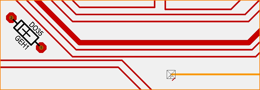
Image: We would like to connect the track on the right (yellow) with the anode of the diode (pad no. 1, left), but the direct way
is blocked by already laid tracks. Now we push them aside as far as necessary to connect the track to the pad of the diode.
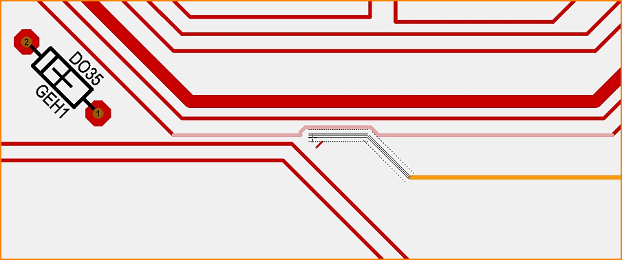
Image: As soon as you touch a foreign track, its segment becomes a phantom line and indicates what the new routing structure
will look like. The design rules, espacially the spacing constraints are kept. The minimum distance between the two tracks is
defined by the largest of the following four values: aura, sinal distance, design rule minimum distance and layer distance
(=a signal can have different minimum distances on different layers).
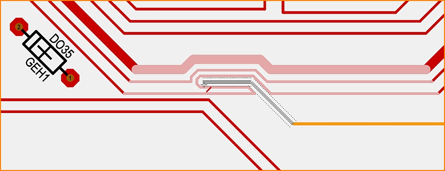
Image: The further one advances to the north, the more get the following tracks affected. In turn they give space as far as needed.
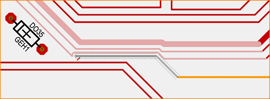
Image: Finally, you can get through the bottleneck without ripping up existing tracks.
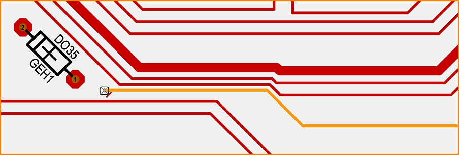
Image: A click always places the penultimate segment first, before a second click places the rest to the cursor position.
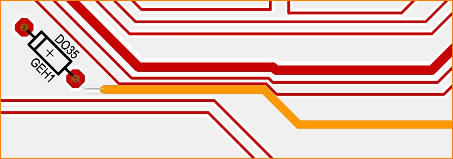
Image: Since we still have activated the "Place track" mode, we can finish the process without interruption.
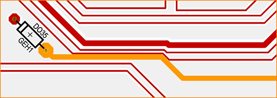
Image: The finished track. In this example, we have displaced more than necessary. If you don't like this, simply use the Undo function.
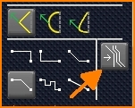
Activate Push and Shove
Push and Shove does not always have to be switched on. If you want to switch it on while routing a track, press the [O] key for options and check the box in the dialog.
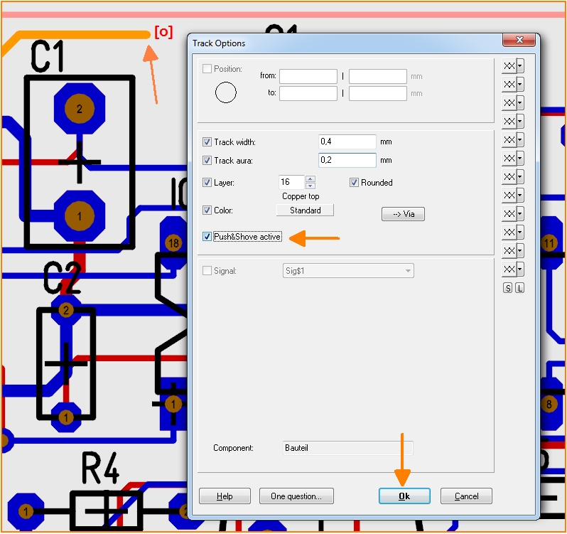
Image: Activate Push&Shove: Check the box in the "Track Options" dialog


