Difference between revisions of "Multisymbol"
| Line 12: | Line 12: | ||
[[image: multisymbol3.jpg|none|Drawing functions: Open Rectangle]]Figure: Drawing functions: Select "Open (unfilled) rectangle"<br><br><br><br> | [[image: multisymbol3.jpg|none|Drawing functions: Open Rectangle]]Figure: Drawing functions: Select "Open (unfilled) rectangle"<br><br><br><br> | ||
[[image: multisymbol4.jpg|none|Rectangles drawn]]Figure: Rectangles drawn as body of the sub symbols (any form is possible). <br><br><br><br> | [[image: multisymbol4.jpg|none|Rectangles drawn]]Figure: Rectangles drawn as body of the sub symbols (any form is possible). <br><br><br><br> | ||
| − | [[image: multisymbol5_e.jpg|none| | + | [[image: multisymbol5_e.jpg|none|Double click on a pin: Change pins]]Figure: Double click each Pin and set its function.<br><br><br><br> |
| − | [[image: multisymbol6_e.jpg|none| | + | [[image: multisymbol6_e.jpg|none|Use text tool and click at position]] Figure: Use text tool (key ["]) and click above black frame. Select text func"tion ''Symbol name''.<br><br><br><br> |
[[image: multisymbol7_e.jpg|none|Textfunktion wählen und auf Position klicken]]Figure: Unterhalb des Textkörpers die Textfunktion ''Bauteilwert'' wählen und per OK absetzen. <br><br><br><br> | [[image: multisymbol7_e.jpg|none|Textfunktion wählen und auf Position klicken]]Figure: Unterhalb des Textkörpers die Textfunktion ''Bauteilwert'' wählen und per OK absetzen. <br><br><br><br> | ||
[[image: multisymbol8_e.jpg|none|Variablen (!) für Symbolname und Bauteilwert gesetzt]]Figure: Beim zweiten Subsymbol genau so verfahren. <br><br><br><br> | [[image: multisymbol8_e.jpg|none|Variablen (!) für Symbolname und Bauteilwert gesetzt]]Figure: Beim zweiten Subsymbol genau so verfahren. <br><br><br><br> | ||
Revision as of 15:26, 13 January 2021
If you want to place certain pin groups of a component symbol at different places in the schematic or on different schematic pages, you can create the component symbol so that it consists of several sub-symbols (pin groups). The individual sub-symbols can - one after the other - be brought into the schematic and placed separately.
To make it quick: When drawing (creating) the symbol, you mark such a pin group (sub symbol) and set its own handle cross using the keyboard key [y]. Do this for all pin groups. Finally, mark everything and save it with [x].
In detail.
We are in schematic view.
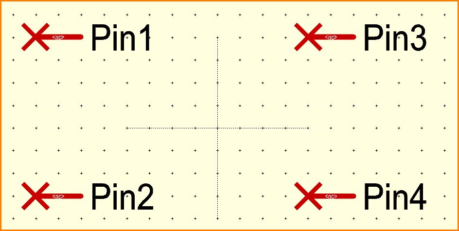
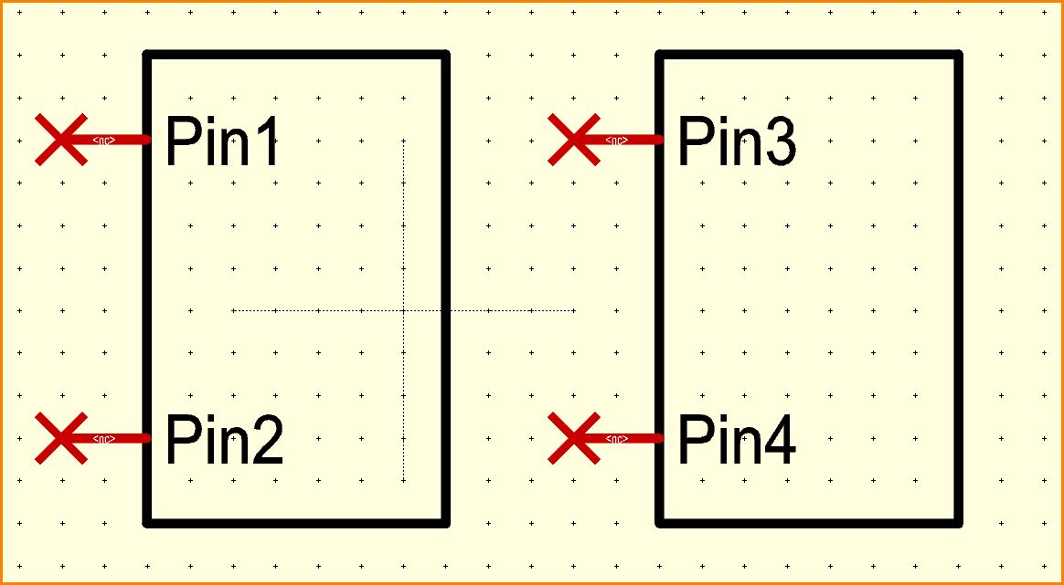
Figure: Four pins placed one after the other by click, numbers 1 to 4 are given automatically. At the shaft of the pin, where <nc> shows, later the signal name will show up, as soon as connected.
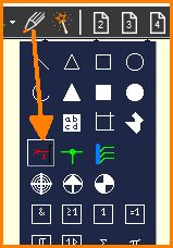
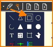
Figure: Drawing functions: Select "Open (unfilled) rectangle"
Figure: Rectangles drawn as body of the sub symbols (any form is possible).
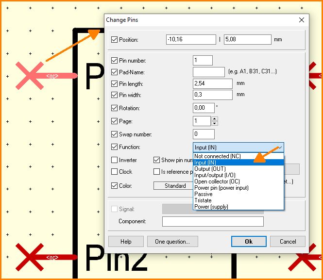
Figure: Double click each Pin and set its function.
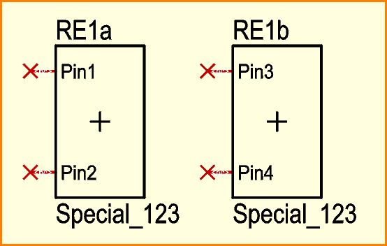
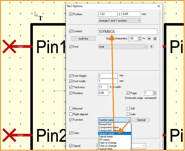
Figure: Use text tool (key ["]) and click above black frame. Select text func"tion Symbol name.
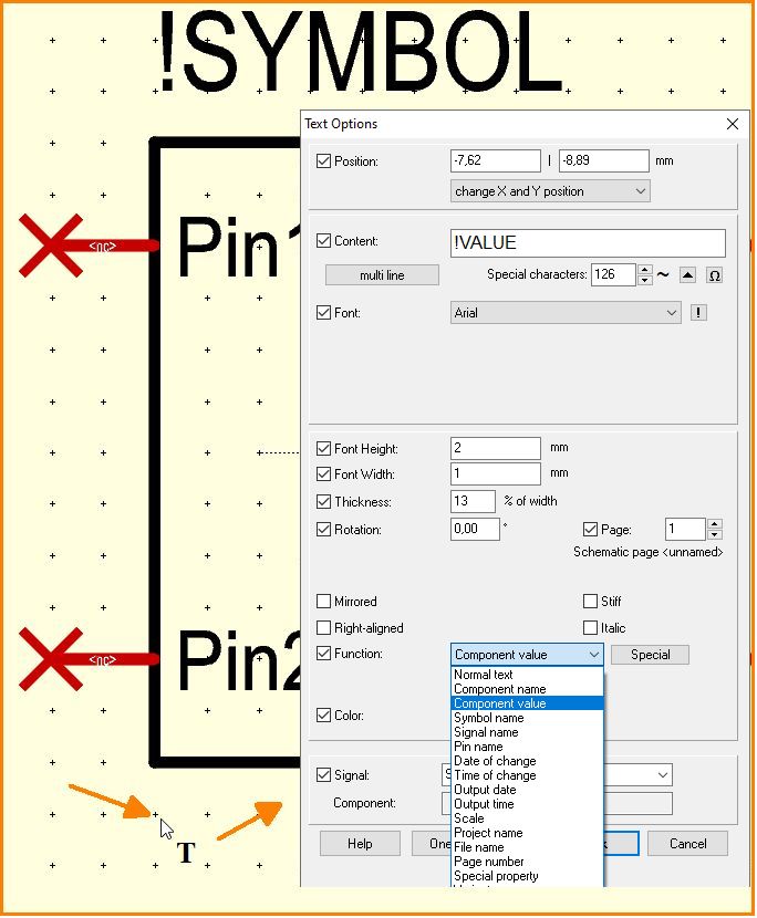
Figure: Unterhalb des Textkörpers die Textfunktion Bauteilwert wählen und per OK absetzen.
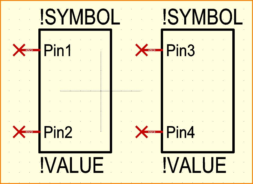
Figure: Beim zweiten Subsymbol genau so verfahren.
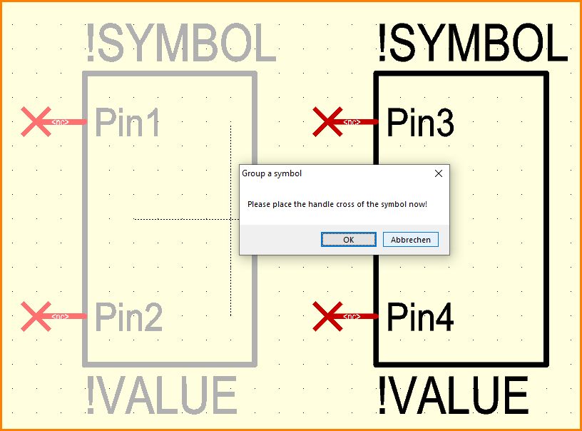
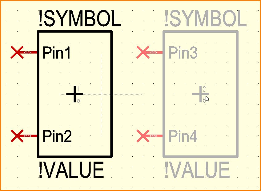
Figure: Jetzt das linke Sub-Symbol mit Fangfenster markieren und Tastaturtaste [y] drücken. Mit OK das Zusammenfassen bestätigen.
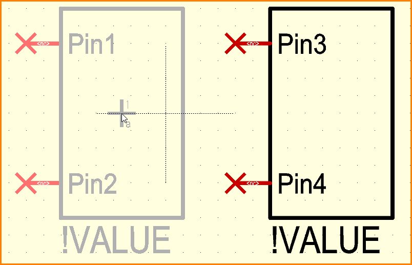
Figure: Mit Mausklick das Griffkreuz setzen, z. B. ins Zentrum.
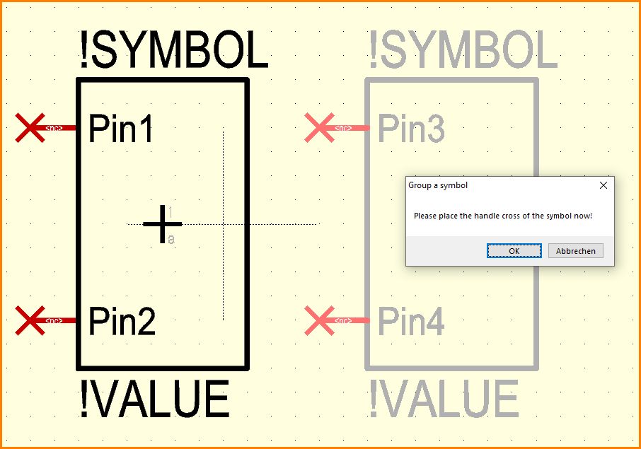
Figure: Beim rechten Sub-Symbol genau so verfahren: Alle Elemente markieren und [y] drücken. Mit OK Das Zusammenfassen bestätigen.
Figure: Mit Mausklick das Griffkreuz setzen, hier auch ins Zentrum.
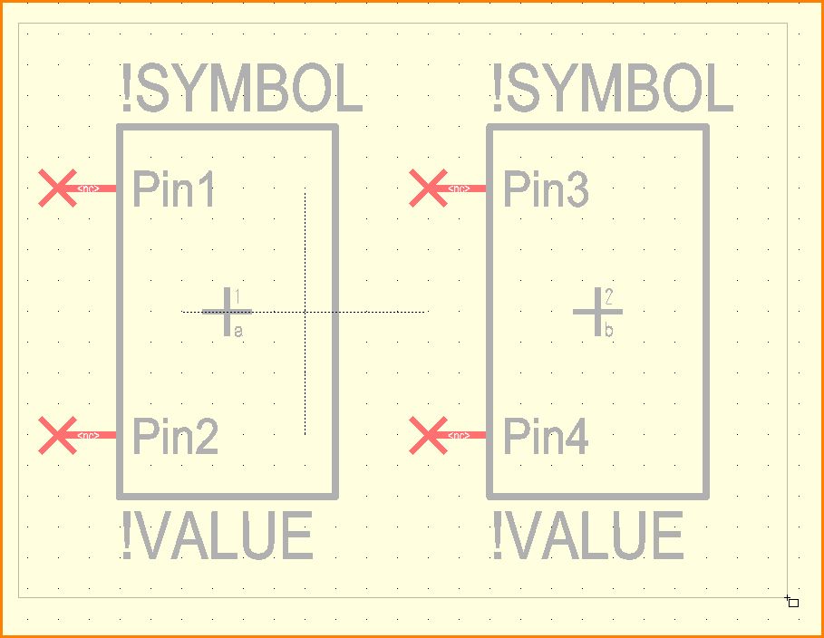
Figure: Jetzt alles markieren und Tastaturtaste [x] drücken, zum Export des Ganzen in die Datenbank (= Abspeichern).
Figure: Export-Dialog bedienen, Gehäuse zuweisen, Speichern, fertig.


![Tastaturtaste [x] drücken und speichern](/wiki/ibfwikien/images/8/8f/Multisymbol14_e.jpg)