Hybrid Autorouter
General
![]()
![]() Also see layout menu "Actions/Automatisms and assistants/Autorouter..."
Also see layout menu "Actions/Automatisms and assistants/Autorouter..."
We start with our example file PIC_route.t3001. After switching to the layout view, the layout shows as follows:
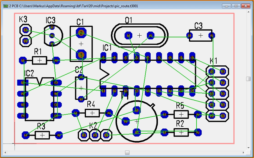
Image: Project unrouted. In green you see the air wires resulting from the connections in the schematic.
How to start the autorouter
Start the Hybrid autorouter in menu "Actions".
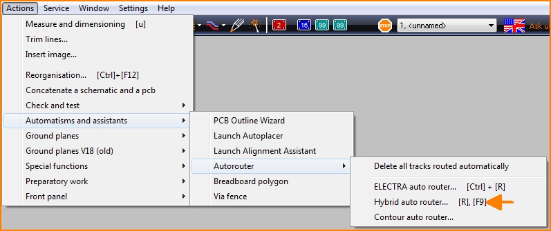
The following view opens:
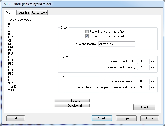
The first section "Signals" shows to the left a list of all signals of the project. Those signals you wish to let routed please highlight by mouseclick. A further click undoes this selection. You can also select several signals and undo the same way.
To the right please enter signal specific settings. The definition of the order has influence on the computing-heuristic. It is difficult to say which setting is best. it depends on the complexity of the layout. In this description we leave the standard setting. The standard settings in the fields Signal tracks and Vias show minimum settings in respect to the production opportunities. You can vary from those. The button "Default" recalls the standard settings.
The second section gives us the opportunity to enter strategic, tactical and operative settings:
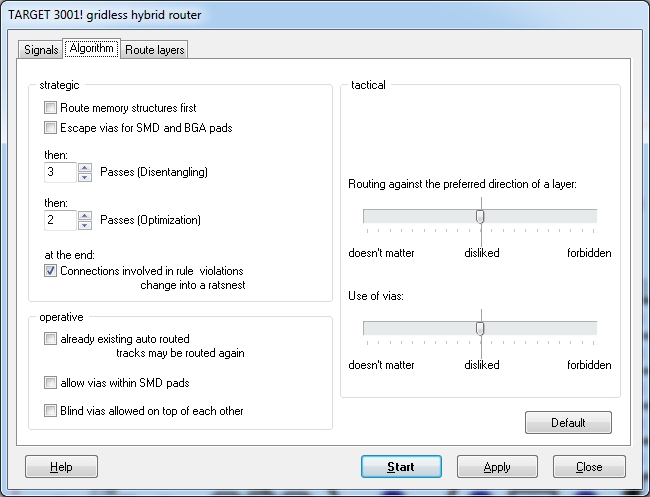
Strategic, tactical, operative settings
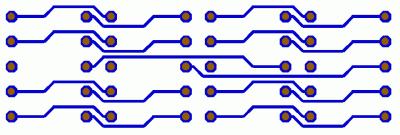
A strategic aspect would be if you are having memory devices in your layout to let them be routed first. In most cases they are routed that way:
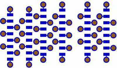
Furthermore SMD- and BGA-Pads should be provided with fan outs. So SMD- or BGA-Pads lying in the same direction as the preferred direction of the router are provided with vias for to make them be reached from layers with opposite (preferred) route direction. In the phase of optimisation only those vias remain which are needed. The following picture could arise:
Enter how much routing and optimisation phases you wish. The routing generates non crossing tracks, the optimisation tightens them and provides them with 45° angles.
Connections which are inflicted in breaks of rules are solved and can be showed as ratsnest (as far as you tick the box). Compute air wires new to receive ratsnest again (menu "Actions"). The settings in area "operational" are activated in later releases of the router.
"Tactical" settings can be done to the right with two sliding buttons. The predefinition of a "preferable direction" makes sense only if you are moving upon two or more signal layers because vias only make sense in those cases. Both sliding buttons should nor be set to "forbidden" neither to "all the same". It makes sense to forbid a routing against the "preferable direction". Set the slider between "doesn't matter" and "forbidden". The use of vias we leave on "doesn't matter". So we don't wish them but we accept them.
To follow a "preferred direction" allows parallel tracking of lots of tracks which - provided with vias - allow lots of tracks in orthogonal direction upon the opposite copper layer. As soon as one track is placed contrary to the preferred direction, it is like an obstacle. The layout is divided into two sections and a routing beyond this track segment is not possible any more.
Now we reach the section "Route layers:
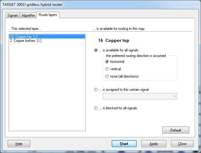
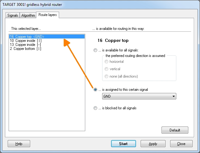
In the left area all project related copper layers are listed. Click upon a desired layer and set on the right side which signals and how they are to be routed upon that layer. You can reserve a layer especially for one single signal (e.g. GND or VCC, as often to be seen on the inner layers of multilayers) or close a layer for all signals. Compare the following picture from another project:
Before you press "Start" to launch the autorouter, consider, whether you should take those router settings to your project. After an dissatisfying routing result you may wish to recall the former settings. Now press "Start" see the progress of the router:
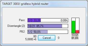
The meaning of the rows and columns:
First row: We see the first of three passes, 33,3% are in progress. Duration of the process: less than 1 minute.
Second row: We see the first disentangeling (routing) pass, right now signal # 18 of 21 is routed, 85,7% of this work is done.
Third row: We see the disentangeling (routing) of signal CS, specifically the first of two signal islands of this signal. Just 50% of the work has been done. The number 556 has an internal computing meaning, take it as a sign for the routing progress.
The green column grows, the red one shrinks. Sign of the success. Right now 17 of 21 signals are routed, thus 81.0 %. At the end of the process the following picture can be seen:
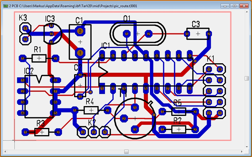
Image: The routing result. The width of the tracks can individually be set for each signal in the schematic.
If the routing result does not satisfy, delete it by dragging a square with M1 over the entire layout and press [Del]. If you have had routed some tracks manually prior to the routing process, those are not deleted unless you press [Del] once more. If you press [Del] once more and all tracks are deleted. Use the undo- function to get them back.
Defining a routing prohibition area
if there are areas in your layout where no tracks are wanted you might define a routing- prohibition area. For doing so you must assign a layer function "Route prohibition" to a certain layer, for example to "copper bottom".
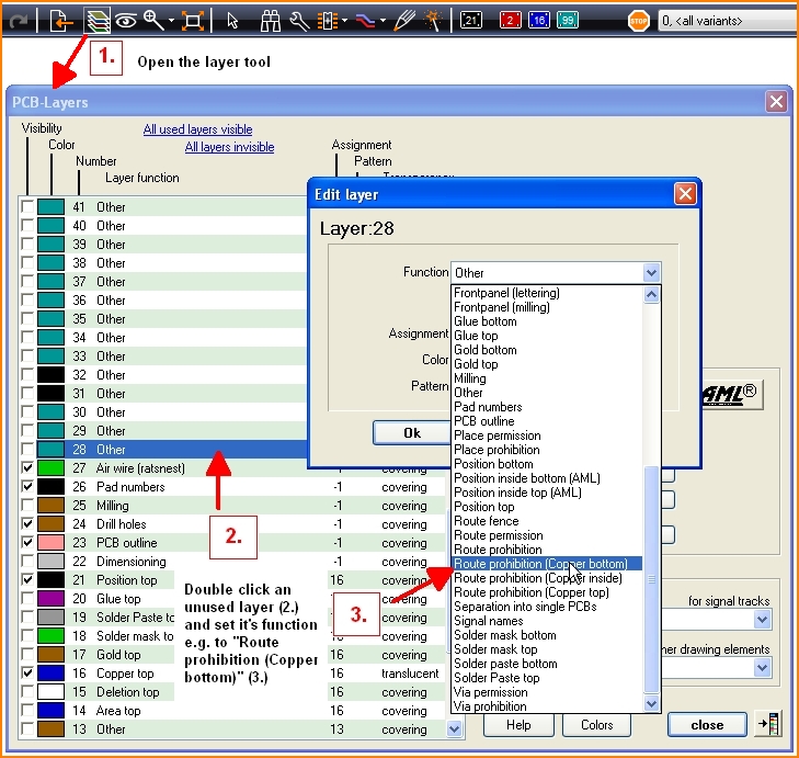
In #2 do a double click on the blue in order to open the "Edit layer" box. It is important to assign the chosen routing prohibition to the desired layer:
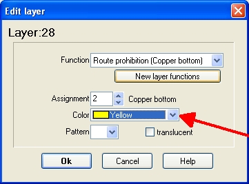
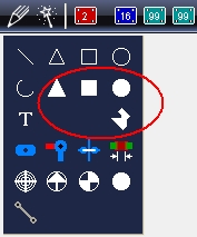
Now draw your routing prohibition area upon this layer by a filled rectangle, circle or polygone using the normal drawing functions.
.

