3D in general
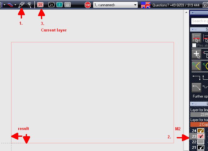
In case you wish to activate the 3D view in TARGET 3001! your layout needs at least a few elements. Please first draw a PCB outline upon layer 23.In case the outline appears too spaceous, adjust it at any time (drag the edges by M1H)...
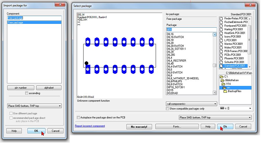
The package browser/the database will guide you regarding the selection of component packages:
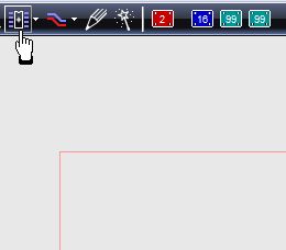
You also might open the package browser from the schematic view:
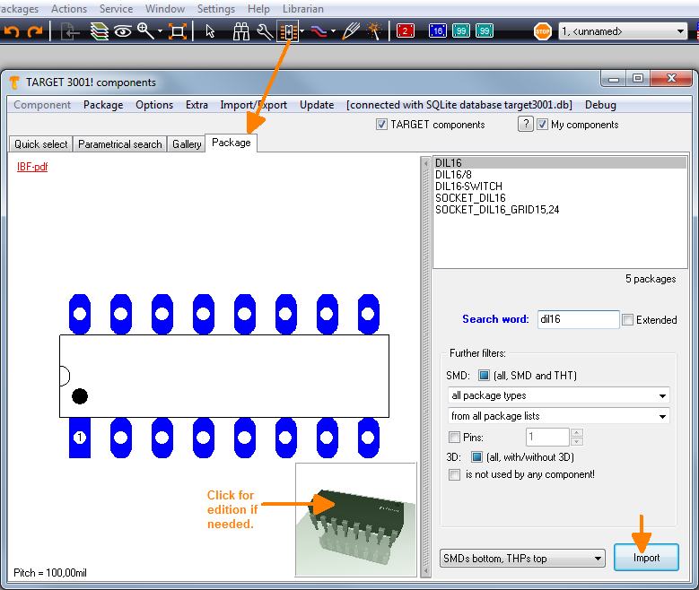
An example: Place a component taken from the "component database" twice to your layout:
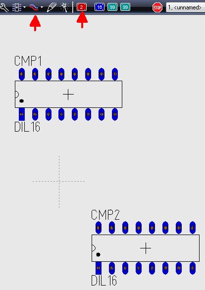
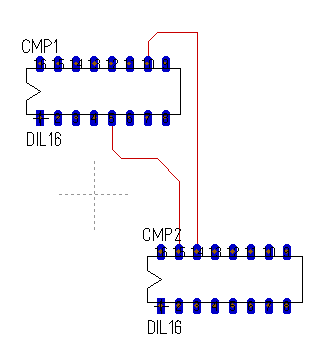
Draw some tracks e.g. on layer 2, copper bottom (red).
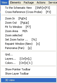
Launch the 3D-view in menu "View":
Or use the button ![]() in the toolbar top right. Now the 3D-Viewer opens:
in the toolbar top right. Now the 3D-Viewer opens:
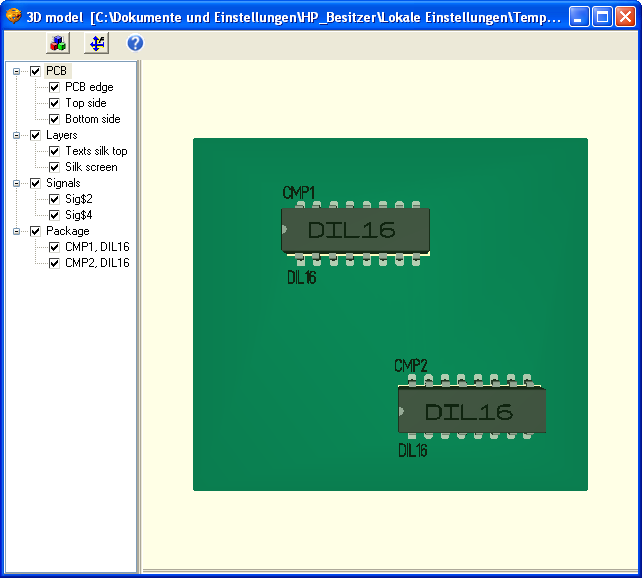
View your layout from all sides by rotating it by mouseclick left
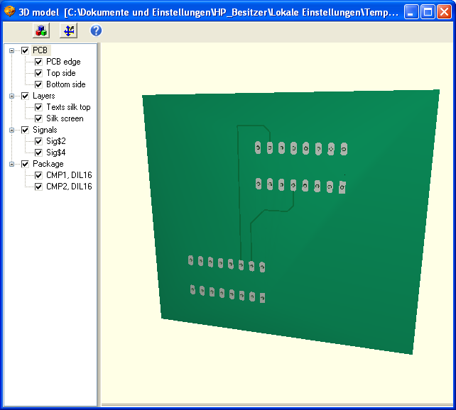
Move the complete view by right mousekey held. Doubleclick it to give it a spin, doubleclick it again to stop it.
Use button ![]() to bring the view to the initial centered position.
to bring the view to the initial centered position.
Use button ![]() to edit the 3D model.
to edit the 3D model.
Select different views from the view bar on the left.
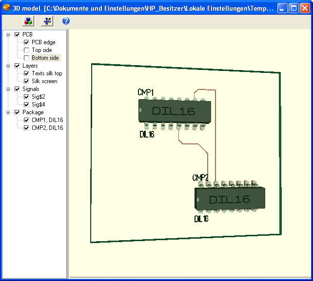
V14 and earlier: Place a component taken from the "standard" library twice to your layout:
Use keys in the tree view
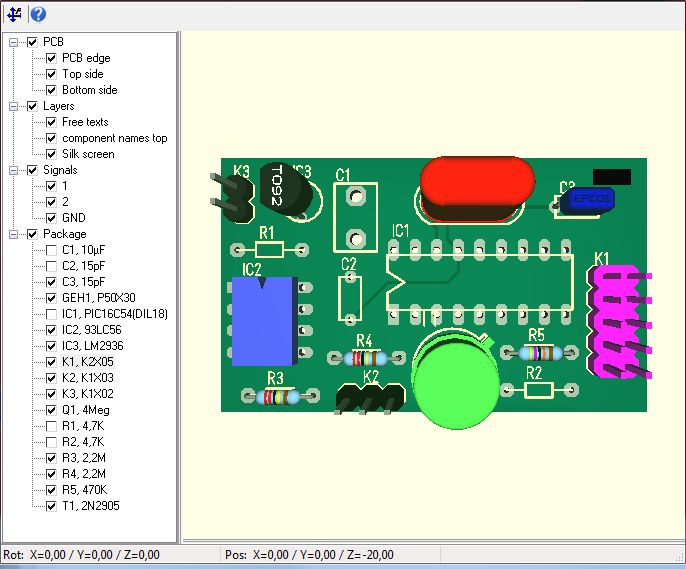
In the tree view it is possible to tick boxes in order to switch the elements they represent on and off (visible, invisible).
With the ENTER key it's possible to highlight them coloured. If you add the CTRL key nomerous parts or signals can be highlighted. The colors blue, red, green and magenta are used sequently. The colors return again in this order.


