Printing script format
If each of your projects requires the printing of a certain set of layer configurations, it can be time consuming and prone to errors to configurate the printer new every time. In such situation it is easier to control the printing by the use of a written command (script). How such a script in TARGET 3001! might look like is explained here.
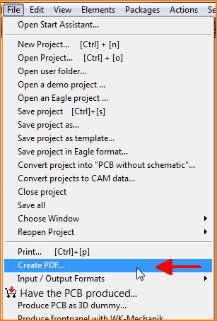
The scripts can also be handled in menu File/Create PDF as well as in the print dialog:

Image: Menu File/Create PDF...
The TARGET 3001! printings can comfortably be controlled by a script language. One script can create several different printings. Every line contains one command. The script commands reflect the settings in the printing dialog. Each line not starting with a key word automatically is recognized as a comment line.
The key words and the command syntax of the TARGET 3001! print scripts are illustrated as follows:
Clear
sets the standard settings:
- not rotated
- not mirrored
- not inverted
- black and white, if schematic
- 1 copy
- blackness 100%
- not only centering drills
- no pictograms
- no background color
- print groundplane lines
- PCB outline counts, if board
- not fit to page
- centered
- scale 100%
- offsetX 0
- offsetY 0
- correction X 1
- correction Y 1
- all pages, if schematic
- no variants
- variant components not invisible
- layers are not subject to change
Printer=Name,Duplex,A4
Select printer by it's name, if applicable Duplex or paper size A5-A2, Legal, Letter, CSheet, DSheet, ESheet
Name=Job
Denominate print job, therefore assign name of the print job
The following keywords will be replaced:
- #P by the project name without extention
- #F by the file name with extention
- #D by the current date yyyy-mm-dd
- #T by the current time hh-mm
- #V by the name of the variant
- #R by the name of the revision
- #Q by the name of the variant-revision
Path=C:\Test\...
Assume path for the output file (works since V16.5.0.55 and only with the PDF printer FreePDF-XP). The same keywords will be replaced like in "Name=". Since V19: In the PDF dialog this is the filename for the PDF, e.g. C:\directory\test.PDF.
In the printing dialog: Execute print job, print sheet(s). If "PDF" can be found in the printer's name, you are asked after the "Print" command, whether the printer is ready again. "Print" does not work, if you are in the PDF dialog.
Since V19, in the PDF dialog: Save the PDF file to the "Path". "PDF" does not work, if you are in the printing dialog.
NewPage
From V19.5.0.84, start a new sheet in the PDF. "NewPage" will not work, if you are in the printer dialog.
Portrait
Sheet in portrait
Landscape
Sheet in landscape
Mirror=True/False
Mirror?
Inverted=True/False
Invert?
Color=True/False
Black-white?
Copies=1
Number of copies
Blackness=100
Grade of blackness in percent
SmallDrill=True/False
Only centering drillings?
Pictograms=True/False
Drillings as pictograms?
BackGround=True/False
Print background color?
GroundLines=True/False
Print ground lines?
PCBOutline=True/False
PCB outline counts?
SheetFit=True/False
Fit to sheet?
Center=True/False
Centering to the sheet?
Scale=100
Scale in percent
OffsetX=0
Horizontal offset in mm
OffsetY=0
Vertical offset in mm
CorrectX=1.0
Horizontal adjustment factor
CorrectY=1.0
Vertical adjustment factor
Pages=No/All/1-3
Which pages get printed? No (= only the current page); All; 1-3 (= pages one to three)
Variants=True/False
Print variants?
HideVariant=True/False
Shall variant parts be faded out?
Variant=Clear/Special
Print this variant as well. The name of the variant will be passed. Clear = reset all variants
LayerOff=All/0,1,2,23
These layers will be faded out. All = all
LayerOn=0,1,2,23
These layers will be faded in
LayerButton=3
This programmed layer button in the sidebar will be pressed and the layers contained get faded in
ShowNames=True/False
Show the component names in schematic view?
ShowValues=True/False
Show the component values in schematic view?
View=SCH/PCB
Toggle to the schematic or PCB view.

