Guided Bus Router: Difference between revisions
Created page with "This allows you to route several tracks at once, for example the lines of a bus: In the circuit board view, first select the desired air lines specified by the circuit diagram. To do this, drag a catch window with M1H from '''right to left'''. In this case, it is sufficient to touch the air lines: File:Guided1.png<br> (Image 1: Selecting airlines)<br><br> Then type the [Shift] + [B] key for Bus. Now use M1 to start the guide lines to which the bus should or..." |
No edit summary |
||
| Line 1: | Line 1: | ||
This allows you to route several tracks at once, for example the | This allows you to route several tracks at once, for example the tracks of a bus. | ||
In the | In the PCB view, first select the desired airwires specified by the schematic. To do this, drag a catch window with [[M1H]] from '''right to left'''. In this case, it is sufficient to touch the airwires: | ||
[[File:Guided1.png]]<br> | [[File:Guided1.png|alternative text=Selecting airwires]]<br> | ||
(Image 1: Selecting | (Image 1: Selecting airwires)<br><br> | ||
Then type the [Shift] + [B] key for Bus. Now use [[M1]] to start the guide lines to which the bus should orient itself. TARGET uses the current working layer for copper. | Then type the [Shift] + [B] key for Bus. Now use [[M1]] to start the guide lines to which the bus should orient itself. TARGET uses the current working layer for copper. | ||
Do not start too close to the soldering pads so that TARGET can connect the tracks properly afterwards: | Do not start too close to the soldering pads so that TARGET can connect the tracks properly afterwards: | ||
[[File:Guided2.png|alternative text=Start | [[File:Guided2.png|alternative text=Start guide lines]]<br> | ||
(Image 2: Start guide lines)<br><br> | (Image 2: Start guide lines)<br><br> | ||
The current [[ | The current [[bending mode]] is used for the guide lines too. Use [[M2]] to change it. If possible, start and end with a straight section and not with a very short bend. Type [Enter] to define the end of the guide lines: | ||
[[File:Guided3.png|alternative text=End guide lines with [Enter]]]<br> | [[File:Guided3.png|alternative text=End guide lines with [Enter]]]<br> | ||
(Image 3: End guide lines with [Enter])<br><br> | (Image 3: End guide lines with [Enter])<br><br> | ||
TARGET tries to | TARGET tries to route the traces along the guide lines and then connect the solder pads at the end: | ||
[[File:Guided4.png|alternative text=Complete guided bus routing]]<br> | [[File:Guided4.png|alternative text=Complete guided bus routing]]<br> | ||
(Image 4: | (Image 4: Complete guided bus routing)<br><br> | ||
The minimum | The minimum spacing and minimum widths of the signals are automatically taken into account during routing. | ||
Revision as of 12:33, 31 October 2024
This allows you to route several tracks at once, for example the tracks of a bus.
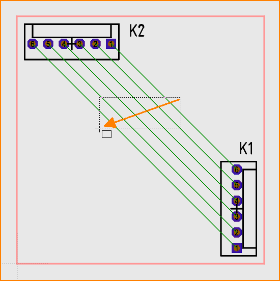
In the PCB view, first select the desired airwires specified by the schematic. To do this, drag a catch window with M1H from right to left. In this case, it is sufficient to touch the airwires:

(Image 1: Selecting airwires)
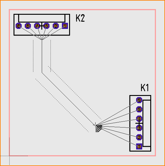
Then type the [Shift] + [B] key for Bus. Now use M1 to start the guide lines to which the bus should orient itself. TARGET uses the current working layer for copper.
Do not start too close to the soldering pads so that TARGET can connect the tracks properly afterwards:

(Image 2: Start guide lines)
The current bending mode is used for the guide lines too. Use M2 to change it. If possible, start and end with a straight section and not with a very short bend. Type [Enter] to define the end of the guide lines:
![alternative text=End guide lines with [Enter]](/wiki/ibfwikien/images/1/14/Guided3.png)
(Image 3: End guide lines with [Enter])
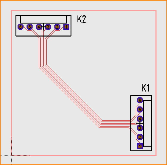
TARGET tries to route the traces along the guide lines and then connect the solder pads at the end:

(Image 4: Complete guided bus routing)
The minimum spacing and minimum widths of the signals are automatically taken into account during routing.

