Create and save a milling pattern: Difference between revisions
Created page with "This article currently is under construction.<br><br> Construct your own milling pattern for use in front panel design in principle like a component package:<br><br> *Draw o..." |
No edit summary |
||
| Line 18: | Line 18: | ||
First set the grid to 0.1mm, a tenth of a millimeter. Select the open rectangle from the drawing functions (pencil icon). Hover on the color field of the plane ''29, Front panel (contours)'' and click with the right mouse button. This layer is now activated for drawing. Roughly draw a rectangle around the coordinate origin. Double-click on one of its lines and define width and height 32 x 23 mm. At the same time, assign the coordinate origin to the center (upper part of the dialog).<br><br> | First set the grid to 0.1mm, a tenth of a millimeter. Select the open rectangle from the drawing functions (pencil icon). Hover on the color field of the plane ''29, Front panel (contours)'' and click with the right mouse button. This layer is now activated for drawing. Roughly draw a rectangle around the coordinate origin. Double-click on one of its lines and define width and height 32 x 23 mm. At the same time, assign the coordinate origin to the center (upper part of the dialog).<br><br> | ||
[[Image:Fraesbild1_d.jpg|none]]Image: | [[Image:Fraesbild1_d.jpg|none]]Image: Rectangle with coordinate origin in the center | ||
<br><br> | <br><br> | ||
Move the mouse pointer to the upper left corner of the rectangle and press the [+] key to exactly hit the coordinates of the corner point. Press Return and then press the [g] key to "dra<u>g</u>" the corner point inwards. Do not use the mouse for this, but rather the arrow key on the keyboard. So you stay at the same height and move on the grid only to the right. Look at the coordinates in the status bar at the bottom of the window. When you have reached -10|11.5, press Return.<br><br> | |||
[[Image:Fraesbild2_d.jpg|none]]Image: | [[Image:Fraesbild2_d.jpg|none]]Image: Drag corner inwards | ||
<br><br> | <br><br> | ||
Revision as of 13:15, 25 July 2019
This article currently is under construction.
Construct your own milling pattern for use in front panel design in principle like a component package:
- Draw on plane 29, Front panel (contours)
- Use the standard drawing functions
- Write comments on level 30, front panel (documentation). They are not milled or engraved.
- Highlight all and use keyboard key [x] to set a handle cross.
- Select front panel as component type
- Give it a meaningful name
- Save it, done
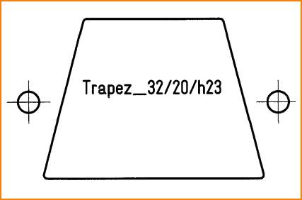
An example: You want to create a trapezoidal excavation with two drill holes on the right and left.

Image: base side=32mm, opposite side=20mm, height h=23mm, hole diameter=3,1mm
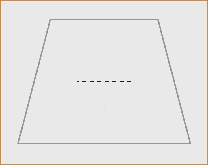
First set the grid to 0.1mm, a tenth of a millimeter. Select the open rectangle from the drawing functions (pencil icon). Hover on the color field of the plane 29, Front panel (contours) and click with the right mouse button. This layer is now activated for drawing. Roughly draw a rectangle around the coordinate origin. Double-click on one of its lines and define width and height 32 x 23 mm. At the same time, assign the coordinate origin to the center (upper part of the dialog).
Image: Rectangle with coordinate origin in the center
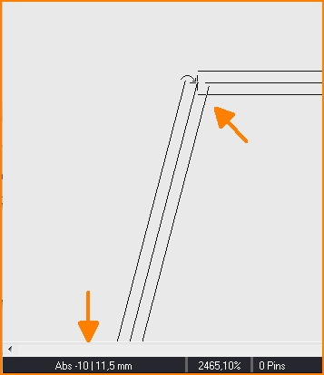
Move the mouse pointer to the upper left corner of the rectangle and press the [+] key to exactly hit the coordinates of the corner point. Press Return and then press the [g] key to "drag" the corner point inwards. Do not use the mouse for this, but rather the arrow key on the keyboard. So you stay at the same height and move on the grid only to the right. Look at the coordinates in the status bar at the bottom of the window. When you have reached -10|11.5, press Return.

Image: Drag corner inwards
Verfahren Sie mit der rechten Ecke genau so.

Image: So könnte das fertige Trapez jetzt aussehen.
Runden Sie die Ecken ggf. ab indem Sie eine Linie markieren und mit Rechtsklick auf eines der schwarzen Endkästchen das Kontextmenü öffnen. Hier gibt es die Option "Knick abrunden" und folgend den Dialog zur Dimensionierung der Rundung.
Setzen Sie nun die beiden Bohrungen mit Durchmesser 3,1mm auf Maß rechts und links daneben. Hierzu können Sie entweder den "Offenen Kreis" aus den Zeichenfunktionen verwenden, oder die Bohrung aus der Sidebar links. Jedes vorhandene Fräsbild der Sidebar kann je nach Bedarf verwendet werden. Gleichermaßen verfahtren Sie mit Text, den Sie allerdings auf Ebene 30 platzieren:
Image: Bohrungen gesetzt, Text vorbereitet...

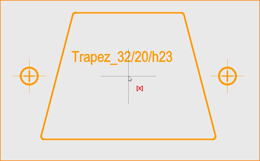
Image: So könnte das Trapez mit Bohrlöchern jetzt aussehen.
Markieren Sie alles und schweben Sie mit der Maus auf die gewünschte Position des Griffkreuzes, sagen wir auf den Koordinatenursprung (könnte auch anderswo sitzen). Tastaturtaste [x] drücken zum Abspeichern. Mit Return Dialoge bestätigen. Als Bauteiltyp Frontplatte wählen und einen sinnvollen Namen vergeben. Abspeichern, fertig. Den eventuell erscheinenden Dialog zum Ändern einfach schließen, sofern alles OK ist. Das Fräsbild verschwindet von der Zeichenfläche in die Bauteildatenbank, wo sie es unter seinem Namen als Bauteiltyp Frontplatte wieder finden.
Zu diesem Thema habe ich eine Frage

