Molded Interconnect Device (MID): Difference between revisions
No edit summary |
No edit summary |
||
| Line 10: | Line 10: | ||
|} | |} | ||
{|cellspacing="5" cellpadding="10" | {|cellspacing="5" cellpadding="10" | ||
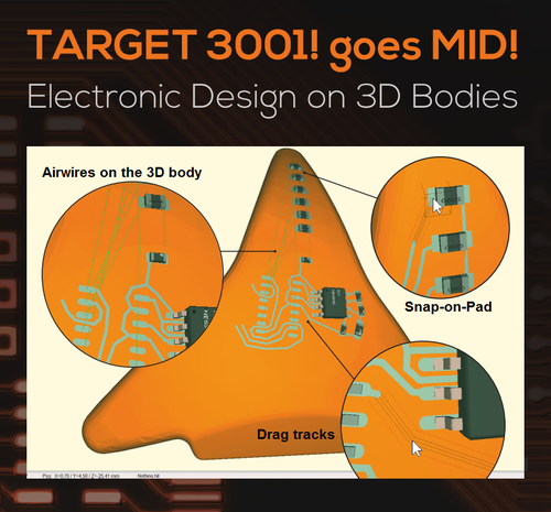
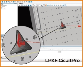
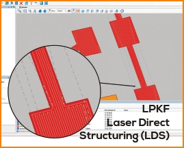
|PCBs waste space, have weight and cost money. If you only need something to hold and connect your electronics components, think about an MID. In many cases an existing plastic part could do the job. TARGET 3001! lets electronics developers work how they are used to: Create a schematic, import the MID as a STEP file, place the packages on the arbitrarily formed MID, see the airwires on the MID body and draw the tracks. The design rule check tells whether all packages are placed, all connections are established and no spacing violations occur<br><br><b>TARGET 3001! presents 3D circuit design</b><br><br>The width and spacing of the tracks can be determined by the constraints in the schematic. An automatic snap-on-pad and snap-on-track as well as the possibility to drag track corners help the designer to easily connect all nets. | |PCBs waste space, have weight and cost money. If you only need something to hold and connect your electronics components, think about an MID. In many cases an existing plastic part could do the job. TARGET 3001! lets electronics developers work how they are used to: Create a schematic, import the MID as a STEP file, place the packages on the arbitrarily formed MID, see the airwires on the MID body and draw the tracks. The design rule check tells whether all packages are placed, all connections are established and no spacing violations occur<br><br><b>TARGET 3001! presents 3D circuit design</b><br><br>The width and spacing of the tracks can be determined by the constraints in the schematic. An automatic snap-on-pad and snap-on-track as well as the possibility to drag track corners help the designer to easily connect all nets. The spacing of each track is also displayed during placement and dragging.||One swift click on a button lets the developer directly export the required 3D STEP file towards the LPKF Cicuit-Pro software. The pads and tracks can now be assigned to certain lasering poses and to the respective laser unit, if more than one are available on the LPKF laser machine. Now the working path of the laser structuring can be computed and the production can begin immediately.<br><br>TARGET 3001! also exports the centers of the pads and the appropriate normal angles to dispense solder paste or conducting glue. The bill of material can be output with the X/Y/Z coordinates of the components and their azimuth and zenith angle for automatic assembly.<br><br> | ||
[http://office.ibfriedrich.com/kunden/electronica/TARGET_MID_A5hoch_electronica.pdf Flyer-Download]<br><br><br><br> | [http://office.ibfriedrich.com/kunden/electronica/TARGET_MID_A5hoch_electronica.pdf Flyer-Download]<br><br><br><br> | ||
|} | |} | ||
Revision as of 12:55, 3 November 2016
WORLD DEBUT at electronica!Design directly on a 3D-body (Molded Interconnect Device, MID) with TARGET 3001! |

|
| PCBs waste space, have weight and cost money. If you only need something to hold and connect your electronics components, think about an MID. In many cases an existing plastic part could do the job. TARGET 3001! lets electronics developers work how they are used to: Create a schematic, import the MID as a STEP file, place the packages on the arbitrarily formed MID, see the airwires on the MID body and draw the tracks. The design rule check tells whether all packages are placed, all connections are established and no spacing violations occur TARGET 3001! presents 3D circuit design The width and spacing of the tracks can be determined by the constraints in the schematic. An automatic snap-on-pad and snap-on-track as well as the possibility to drag track corners help the designer to easily connect all nets. The spacing of each track is also displayed during placement and dragging. |
One swift click on a button lets the developer directly export the required 3D STEP file towards the LPKF Cicuit-Pro software. The pads and tracks can now be assigned to certain lasering poses and to the respective laser unit, if more than one are available on the LPKF laser machine. Now the working path of the laser structuring can be computed and the production can begin immediately. TARGET 3001! also exports the centers of the pads and the appropriate normal angles to dispense solder paste or conducting glue. The bill of material can be output with the X/Y/Z coordinates of the components and their azimuth and zenith angle for automatic assembly. |
Oct 08.-11. 2016, Munich |
Watch live demonstrations at the stand of PCB-POOL, Hall B4, Stand 351. Meet Mr. Harald Friedrich there, head of TARGET 3001! |


