RFID: Difference between revisions
No edit summary |
No edit summary |
||
| Line 1: | Line 1: | ||
'''RFID''' (Radio Frequency IDentification) allows identification and localisation of objects and/or living beings. One needs a '''transponder''' and a '''reading device'''. The transponder is nothing more than a chip being fixed to the object or being embedded into it. This chip puts out a code as soon as it passes the reading device. This code will be interpreted by a software and all information can be generated in clear words. | '''RFID''' (Radio Frequency IDentification) allows identification and localisation of objects and/or living beings. One needs a '''transponder''' and a '''reading device'''. The transponder is nothing more than a chip being fixed to the object or being embedded into it. This chip puts out a code as soon as it passes the reading device at a certain disctance. This code will be interpreted by a software and all information can be generated in clear words. | ||
In order to enlarge the reading distance between transponder and reading device, a little antenna structur can be added to the chip. This might be embedded to the chip itself or externally designed.<br><br> | |||
[[Image:rfidtag.jpg]]<br> | [[Image:rfidtag.jpg]]<br> | ||
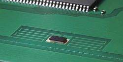
An RFID chip connected to an antenna structure embedded to a ground plane.<br><small>Image source::[http://www.murata.com/new/news_release/2008/pdf/nr0851e.pdf http://www.murata.com/new/news_release/2008/pdf/nr0851e.pdf]</small><br><br> | |||
''' | '''Important''': The RFID chip has nothing to do with the electrical logic of the board. It is electrocally completely independent.<br>The energy required is supplied by the magnetic field of the reading device.<br><br> | ||
The combination of chip and antenna might be very small and e.g. can be designed on foil. So it is very easy to fix such an RFID tag to any object. Why shouldn't a PCB be furnished with such a tag for identification or localisation at any step of further process chain control? At any time e.g. during the process of assembly the board individually can be located and identified. | |||
The PCB house '''PCB-POOL®''' offers '''[http://www.pcb-pool.com/ppde/info_pcbpool_rfid.html Magic PCB®]''', a technique to embed an RFID tag laterally to the edge of a board and connect it to an antenna from the inside. Then it gets resin cast ans thus irreversibly is fixed to the PCB. From the outside only the antenna structure can be seen. | |||
This 2min Film illustrates the layoutprozess in TARGET 3001!:<br><br> | |||
[[Image:rfid_filmab.jpg|link=http://www.target-3001.de/target/video/v16/e/rfid/magic_pcb.html]]<br><br> | [[Image:rfid_filmab.jpg|link=http://www.target-3001.de/target/video/v16/e/rfid/magic_pcb.html]]<br><br> | ||
In TARGET 3001! there are e.g. these antenna geometries available: | |||
In TARGET 3001! | |||
<blockquote> | <blockquote> | ||
| Line 37: | Line 24: | ||
'''LXMS31ACNA-012'''</blockquote><br><br> | '''LXMS31ACNA-012'''</blockquote><br><br> | ||
Load them to your | Load them to your layout like a component from the database and embed them to your groundplane (if there is one). <br><br> | ||
[[image:rfid.jpg]]<br>Antenna geometries<br><br><br> | [[image:rfid.jpg]]<br>Antenna geometries<br><br><br> | ||
[[fr:RFID]][[de:RFID]] | [[fr:RFID]][[de:RFID]] | ||
Revision as of 11:29, 10 April 2013
RFID (Radio Frequency IDentification) allows identification and localisation of objects and/or living beings. One needs a transponder and a reading device. The transponder is nothing more than a chip being fixed to the object or being embedded into it. This chip puts out a code as soon as it passes the reading device at a certain disctance. This code will be interpreted by a software and all information can be generated in clear words.
In order to enlarge the reading distance between transponder and reading device, a little antenna structur can be added to the chip. This might be embedded to the chip itself or externally designed.

An RFID chip connected to an antenna structure embedded to a ground plane.
Image source::http://www.murata.com/new/news_release/2008/pdf/nr0851e.pdf
Important: The RFID chip has nothing to do with the electrical logic of the board. It is electrocally completely independent.
The energy required is supplied by the magnetic field of the reading device.
The combination of chip and antenna might be very small and e.g. can be designed on foil. So it is very easy to fix such an RFID tag to any object. Why shouldn't a PCB be furnished with such a tag for identification or localisation at any step of further process chain control? At any time e.g. during the process of assembly the board individually can be located and identified.
The PCB house PCB-POOL® offers Magic PCB®, a technique to embed an RFID tag laterally to the edge of a board and connect it to an antenna from the inside. Then it gets resin cast ans thus irreversibly is fixed to the PCB. From the outside only the antenna structure can be seen.
This 2min Film illustrates the layoutprozess in TARGET 3001!:
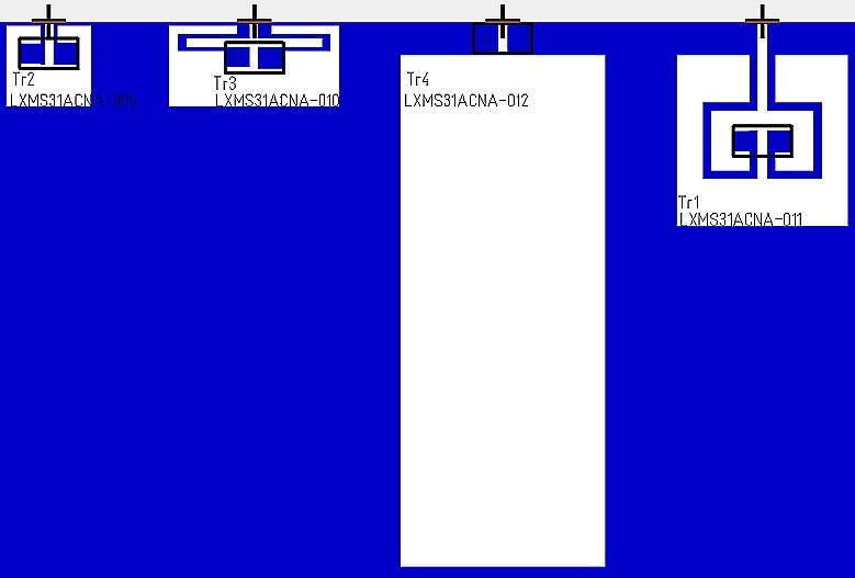
In TARGET 3001! there are e.g. these antenna geometries available:
LXMS31ACNA-009
LXMS31ACNA-010
LXMS31ACNA-011
LXMS31ACNA-012
Load them to your layout like a component from the database and embed them to your groundplane (if there is one).


