Ultra Librarian: Difference between revisions
No edit summary |
No edit summary |
||
| Line 15: | Line 15: | ||
[[Image:UltraLibrarian_4.jpg|Ultra Librarian]]<br>Image: UL offers all three characteristic forms for this component. The views can be varied, see buttons below the images. A click on the Download button opens a dialog to select the CAD tool. In our case it is TARGET 3001!<br><br><br> | [[Image:UltraLibrarian_4.jpg|Ultra Librarian]]<br>Image: UL offers all three characteristic forms for this component. The views can be varied, see buttons below the images. A click on the Download button opens a dialog to select the CAD tool. In our case it is TARGET 3001!<br><br><br> | ||
[[Image:UltraLibrarian_5.jpg|Ultra Librarian]]<br>Image: Tick the box at TARGET 3001! for schematic symbol and footprint pattern. Ticking the box to load the step model (3D view) from V20 | [[Image:UltraLibrarian_5.jpg|Ultra Librarian]]<br>Image: Tick the box at TARGET 3001! for schematic symbol and footprint pattern. Ticking the box to load the step model (3D view) is from V20 not neccessary any more. As soon as a 3D model is offered at UL, TARGET loads it automatically.<br><br><br> | ||
[[Image:UltraLibrarian_6.jpg|Ultra Librarian]]<br>Image: If TARGET is open, the TARGET tab in your taskbar flashes immediately.<br><br><br> | [[Image:UltraLibrarian_6.jpg|Ultra Librarian]]<br>Image: If TARGET is open, the TARGET tab in your taskbar flashes immediately.<br><br><br> | ||
| Line 21: | Line 21: | ||
[[Image:UltraLibrarian_6a.jpg|Ultra Librarian]]<br>Image: Your open TARGET now recognizes that something has come in. Click on the illuminated TAB to fade in TARGET. <br><br><br> | [[Image:UltraLibrarian_6a.jpg|Ultra Librarian]]<br>Image: Your open TARGET now recognizes that something has come in. Click on the illuminated TAB to fade in TARGET. <br><br><br> | ||
[[Image:UltraLibrarian_6b_e.jpg|Ultra Librarian]]<br>Image: You immediately have the corresponding component symbol | [[Image:UltraLibrarian_6b_e.jpg|Ultra Librarian]]<br>Image: You immediately now have the corresponding component symbol at your cursor tip to place it. At the same time it has already been saved to the TARGET component database.<br><br><br> | ||
[[Image:UltraLibrarian_6c_e.jpg|Ultra Librarian]]<br>Image: If you'd like to adapt the shape of the imported symbol, please try the following special function: [[https://server.ibfriedrich.com/wiki/ibfwikien/index.php/Pin#Arrange_pins_according_to_processor_scheme|"Order the pins accorting to a processor scheme"]] in schematic menu Components/Special Functions...<br><br><br> | [[Image:UltraLibrarian_6c_e.jpg|Ultra Librarian]]<br>Image: If you'd like to adapt the shape of the imported symbol, please try the following special function: [[https://server.ibfriedrich.com/wiki/ibfwikien/index.php/Pin#Arrange_pins_according_to_processor_scheme|"Order the pins accorting to a processor scheme"]] in schematic menu ''Components/Special Functions...''<br><br><br> | ||
[[Image:UltraLibrarian_6d_e.jpg|Ultra Librarian]]<br>Image: Now the symbol | [[Image:UltraLibrarian_6d_e.jpg|Ultra Librarian]]<br>Image: Now the symbol looks a bit more ''TARGETish''. Alimentation pins are arranged North and South. If the pins don't bring a "Function" along, it will be set to ''Power''. Pins of which TARGET assumes being ports are put East. They get function ''Input/Output (I/O)''. The pins to the West need to be set separately each by double click. You can rearrange the pins at your own idea simply by moving. <br><br><br> | ||
Revision as of 11:06, 21 December 2018
Download parts from Ultra Librarian. Have them instantly at your cursor tip.
Ultra Librarian (UL) is a portal for downloading CAD data of electronic components. This mainly involves the schematic symbol, the soldering foot pattern and a 3D model. These data can be easily integrated into the TARGET 3001! component database in order to use them in your designs. The following images illustrate the individual steps:
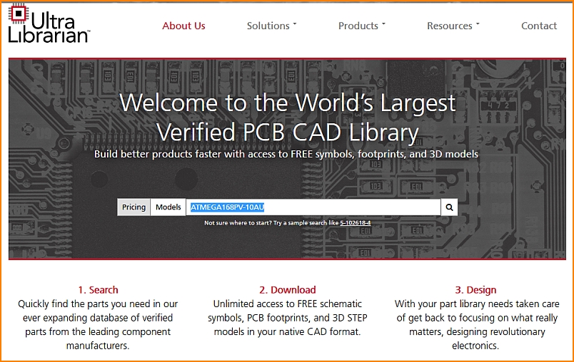
Image: The UL opening dialog. Components can be searched by the name, e.g. ATMEGA168PV-10AU, a microcontroller by Atmel/Microchip.
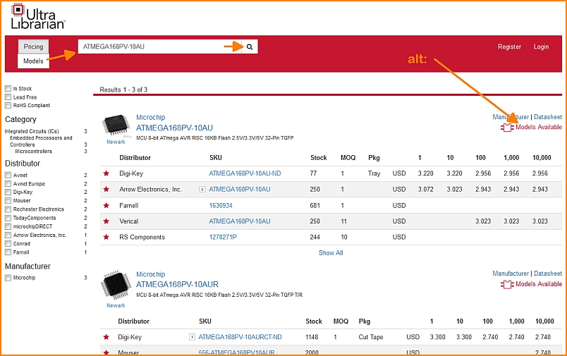
Image: UL list of results. First of all, we are interested in the models, which means the CAD data.
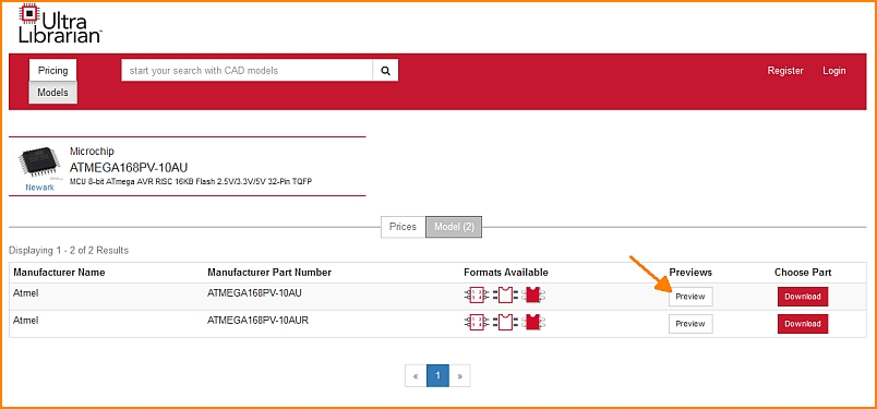
Image: Available models can be seen in the preview which UL offers.
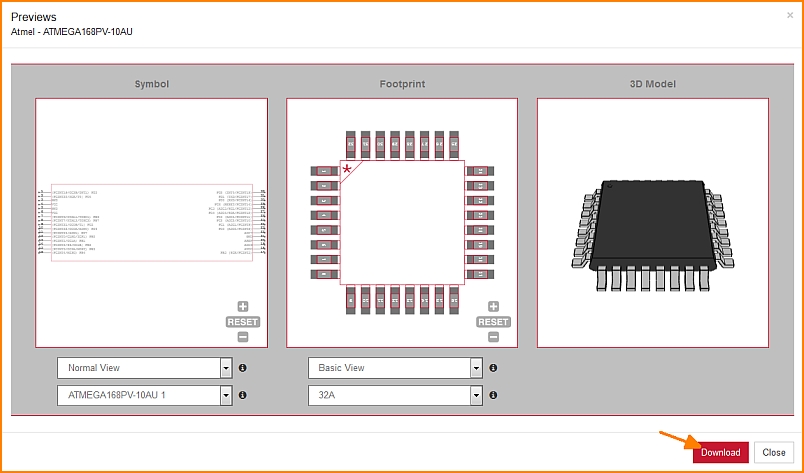
Image: UL offers all three characteristic forms for this component. The views can be varied, see buttons below the images. A click on the Download button opens a dialog to select the CAD tool. In our case it is TARGET 3001!
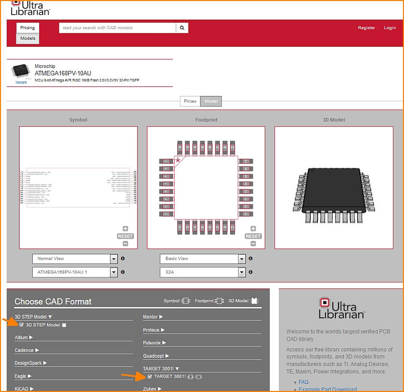
Image: Tick the box at TARGET 3001! for schematic symbol and footprint pattern. Ticking the box to load the step model (3D view) is from V20 not neccessary any more. As soon as a 3D model is offered at UL, TARGET loads it automatically.
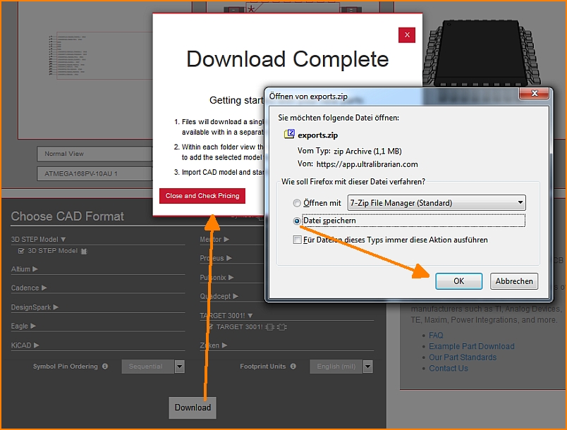
Image: If TARGET is open, the TARGET tab in your taskbar flashes immediately.
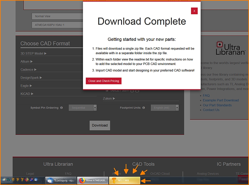
Image: Your open TARGET now recognizes that something has come in. Click on the illuminated TAB to fade in TARGET.
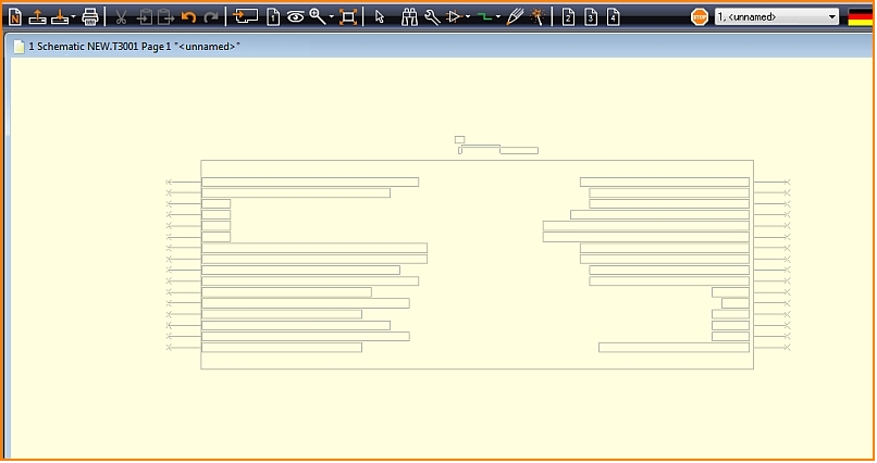
Image: You immediately now have the corresponding component symbol at your cursor tip to place it. At the same time it has already been saved to the TARGET component database.
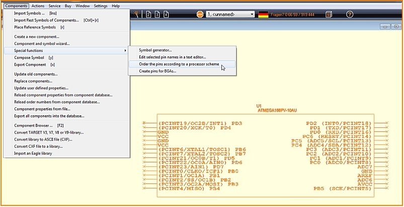
Image: If you'd like to adapt the shape of the imported symbol, please try the following special function: ["Order the pins accorting to a processor scheme"] in schematic menu Components/Special Functions...
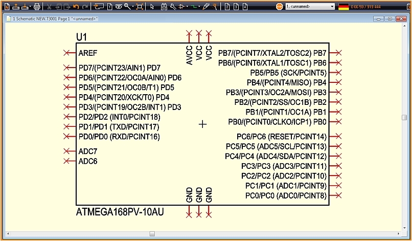
Image: Now the symbol looks a bit more TARGETish. Alimentation pins are arranged North and South. If the pins don't bring a "Function" along, it will be set to Power. Pins of which TARGET assumes being ports are put East. They get function Input/Output (I/O). The pins to the West need to be set separately each by double click. You can rearrange the pins at your own idea simply by moving.
How to handle the downloaded zip file manually
For versions V19 and older.
UL delivers the data in CXF and STEP format. Save the zip file in any directory.
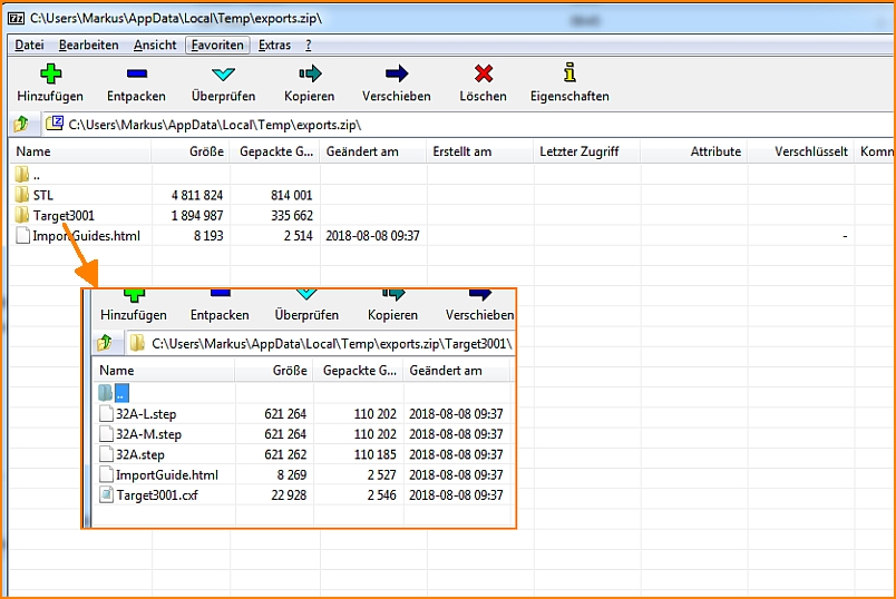
Image: The zip file contains the items shown...
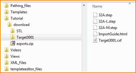
Image: ...and saves them to a directory of your choice.
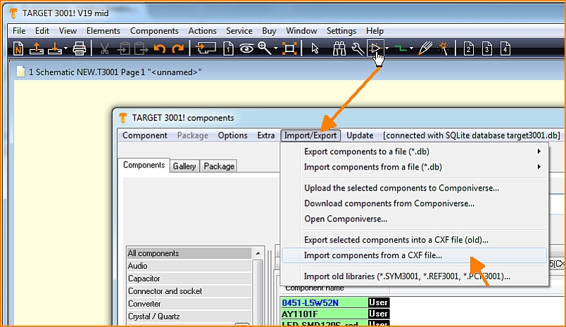
Image: Now open the component database in TARGET 3001! and import the data first as CXF.
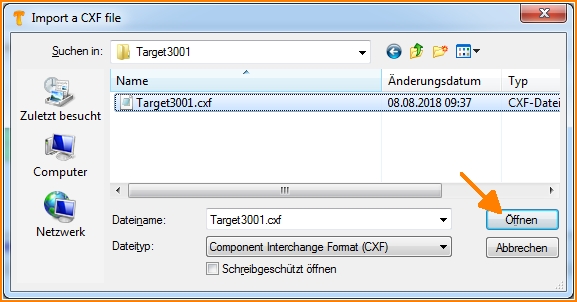
Image: Circuit diagram and solder foot pattern are transmitted by the CXF format.
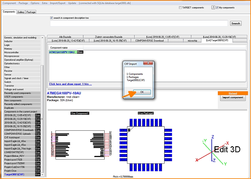
Image: That is how it performs in TARGET 3001!
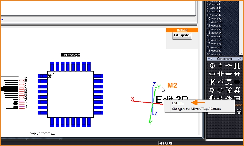
Image: To import the step model for the 3D view, click with the right mouse button on the coordinate system and select the "Edit 3D" option.
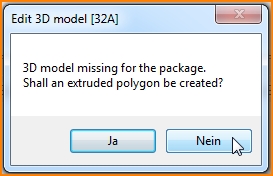
Image: An extruded polygon of the outline shall not be created, because we want to import a nice 3D model. So we choose "No" here.
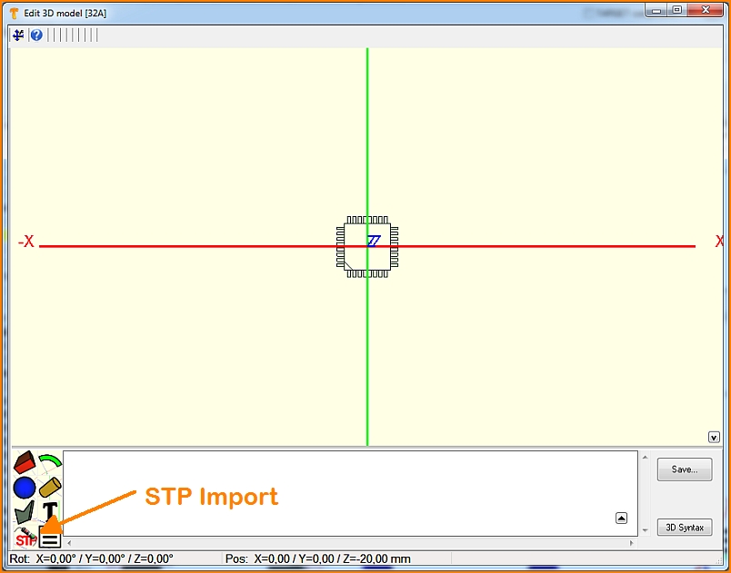
Image: The landing pattern shows a mark in the southeast. Pad number 1 is therefore expected on the south horizontal row, at the left outer position. Now press the button to import a step file.
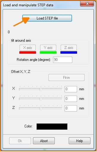
Image: In the dialog that opens, you will be asked to load the corresponding file. It may be necessary to align the model, because the object does not always fit in perfectly.
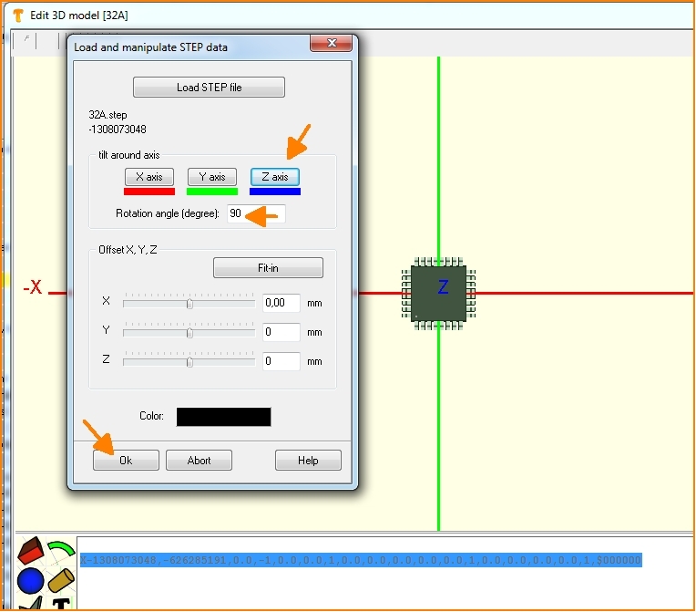
Image: So you can rotate or move the 3D image along the coordinate axes until the image no longer shows any offset.
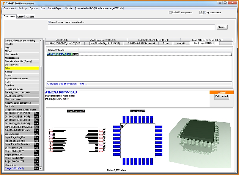
Image: After OK, close all dialogs including the database. Your part is now in the database and can be used for designs in TARGET.


