Ultra Librarian: Difference between revisions
No edit summary |
No edit summary |
||
| Line 6: | Line 6: | ||
[[Image:UltraLibrarian_1.jpg|Ultra Librarian]]<br>Image: The [https://www.ultralibrarian.com UL opening dialog]. Components can be searched by the name, e.g. ''ATMEGA168PV-10AU'', a microcontroller by Atmel/Microchip.<br><br><br> | [[Image:UltraLibrarian_1.jpg|Ultra Librarian]]<br>Image: The [https://www.ultralibrarian.com UL opening dialog]. Components can be searched by the name, e.g. ''ATMEGA168PV-10AU'', a microcontroller by Atmel/Microchip.<br><br><br> | ||
[[Image:UltraLibrarian_2.jpg|Ultra Librarian]]<br>Image: | [[Image:UltraLibrarian_2.jpg|Ultra Librarian]]<br>Image: UL list of results. First of all, we are interested in the models, which means the CAD data.<br><br><br> | ||
[[Image:UltraLibrarian_3.jpg|Ultra Librarian]]<br>Image: Available models can be seen in the preview which UL offers.<br><br><br> | [[Image:UltraLibrarian_3.jpg|Ultra Librarian]]<br>Image: Available models can be seen in the preview which UL offers.<br><br><br> | ||
| Line 14: | Line 14: | ||
[[Image:UltraLibrarian_5.jpg|Ultra Librarian]]<br>Image: Tick the box at TARGET 3001! for schematic symbol and footprint pattern. Also tick the box to load the step model (3D view).<br><br><br> | [[Image:UltraLibrarian_5.jpg|Ultra Librarian]]<br>Image: Tick the box at TARGET 3001! for schematic symbol and footprint pattern. Also tick the box to load the step model (3D view).<br><br><br> | ||
[[Image:UltraLibrarian_6.jpg|Ultra Librarian]]<br>Image: | [[Image:UltraLibrarian_6.jpg|Ultra Librarian]]<br>Image: UL delivers the data in CXF and STEP format. Save the zip file in any directory.<br><br><br> | ||
[[Image:UltraLibrarian_7.jpg|Ultra Librarian]]<br>Image: | [[Image:UltraLibrarian_7.jpg|Ultra Librarian]]<br>Image: The zip file contains the items shown...<br><br><br> | ||
[[Image:UltraLibrarian_8.jpg|Ultra Librarian]]<br>Image: | [[Image:UltraLibrarian_8.jpg|Ultra Librarian]]<br>Image: ...and saves them to a directory of your choice.<br><br><br> | ||
[[Image:UltraLibrarian_9.jpg|Ultra Librarian]]<br>Image: | [[Image:UltraLibrarian_9.jpg|Ultra Librarian]]<br>Image: Now open the component database in TARGET 3001! and import the data first as CXF.<br><br><br> | ||
[[Image:UltraLibrarian_10.jpg|Ultra Librarian]]<br>Image: | [[Image:UltraLibrarian_10.jpg|Ultra Librarian]]<br>Image: Circuit diagram and solder foot pattern are transmitted through the CXF format.<br><br><br> | ||
[[Image:UltraLibrarian_11.jpg|Ultra Librarian]]<br>Image: | [[Image:UltraLibrarian_11.jpg|Ultra Librarian]]<br>Image: That is how it prformss in TARGET 3001!<br><br><br> | ||
[[Image:UltraLibrarian_12.jpg|Ultra Librarian]]<br>Image: | [[Image:UltraLibrarian_12.jpg|Ultra Librarian]]<br>Image: To import the step model for the 3D view, click with the right mouse button on the coordinate system and select the "Edit 3D" option.<br><br><br> | ||
[[Image:UltraLibrarian_13.jpg|Ultra Librarian]]<br>Image: | [[Image:UltraLibrarian_13.jpg|Ultra Librarian]]<br>Image: An extruded polygon of the outline shall not be created, because we want to import a nice 3D model. So we choose "No" here. If a step file lacks, the representation of the component body as an extruded polygon is a fast alternative. The component contour is brought to height so that a cuboid or a cylinder or - depending on the contour - another body is created. <br><br><br> | ||
[[Image:UltraLibrarian_14.jpg|Ultra Librarian]]<br>Image: Das landing pattern zeigt die Markierung im Südosten. Pad Nummer 1 wird also auf der horizontalen Reihe im Süden erwartet und zwar an Position links außen. Drücken Sie jetzt den Knopf zum Import einer Step-Datei.<br><br><br> | [[Image:UltraLibrarian_14.jpg|Ultra Librarian]]<br>Image: Das landing pattern zeigt die Markierung im Südosten. Pad Nummer 1 wird also auf der horizontalen Reihe im Süden erwartet und zwar an Position links außen. Drücken Sie jetzt den Knopf zum Import einer Step-Datei.<br><br><br> | ||
Revision as of 14:29, 9 August 2018
Ultra Librarian (UL) is a portal for downloading CAD data of electronic components. This mainly involves the schematic symbol, the soldering foot pattern and a 3D model. These data can be easily integrated into the TARGET 3001! - component database. The following images illustrate the individual steps:
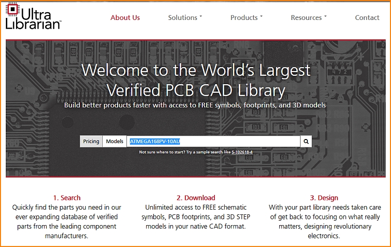
Image: The UL opening dialog. Components can be searched by the name, e.g. ATMEGA168PV-10AU, a microcontroller by Atmel/Microchip.
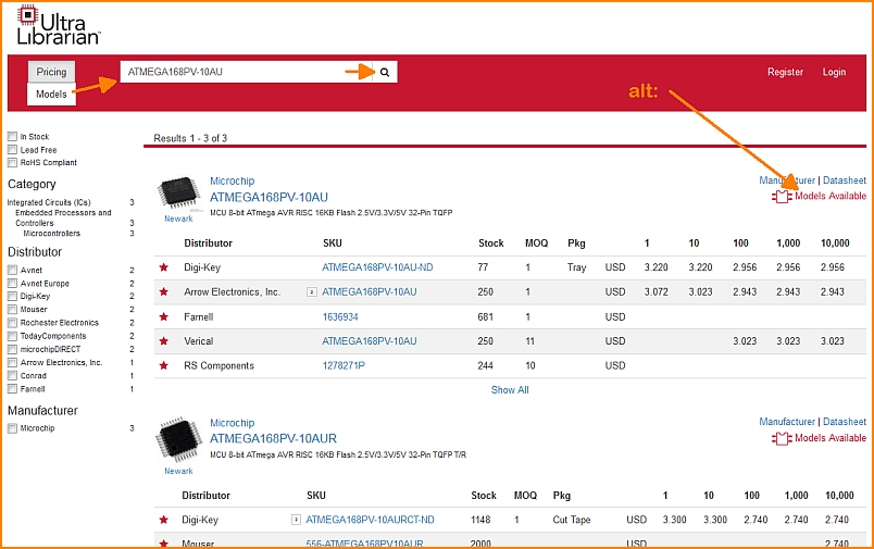
Image: UL list of results. First of all, we are interested in the models, which means the CAD data.
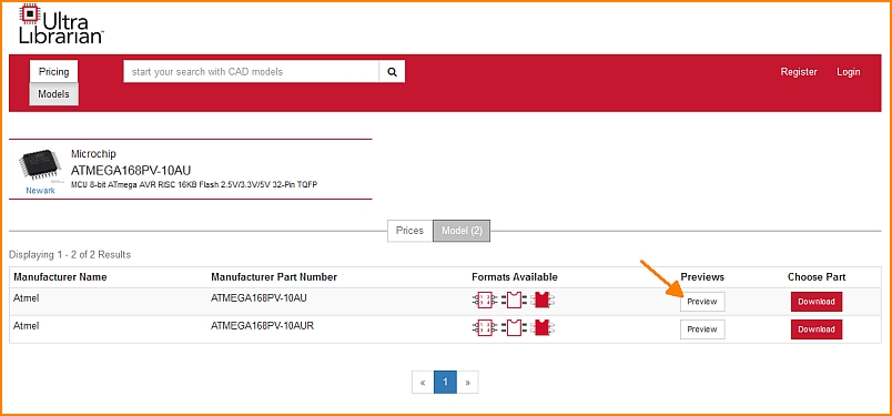
Image: Available models can be seen in the preview which UL offers.
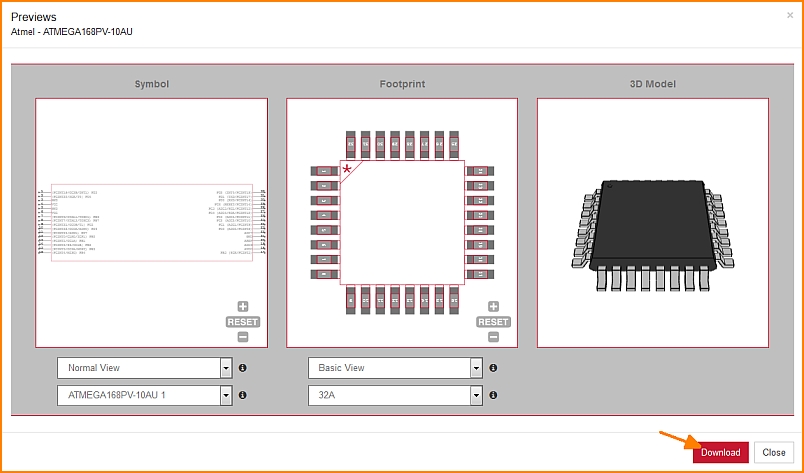
Image: UL offers all three characteristic forms for this component. The views can be varied, see buttons below the images. A click on the Download button opens a dialog to select the CAD tool. In our case it is TARGET 3001!
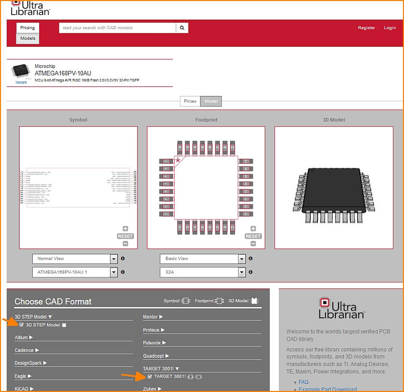
Image: Tick the box at TARGET 3001! for schematic symbol and footprint pattern. Also tick the box to load the step model (3D view).
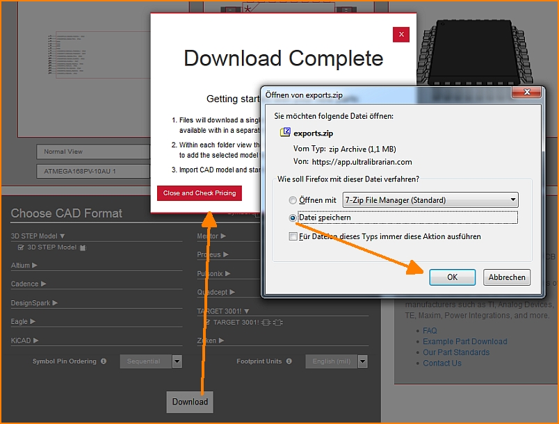
Image: UL delivers the data in CXF and STEP format. Save the zip file in any directory.
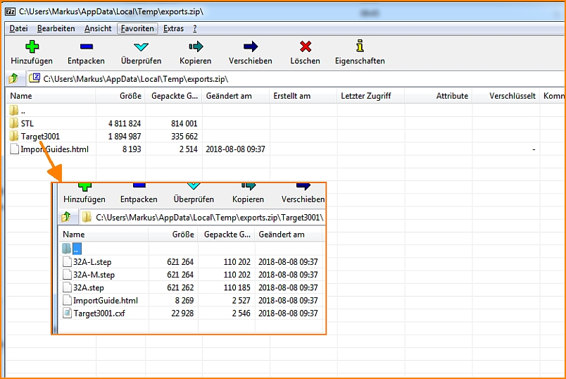
Image: The zip file contains the items shown...
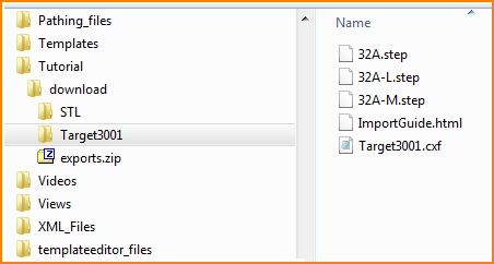
Image: ...and saves them to a directory of your choice.
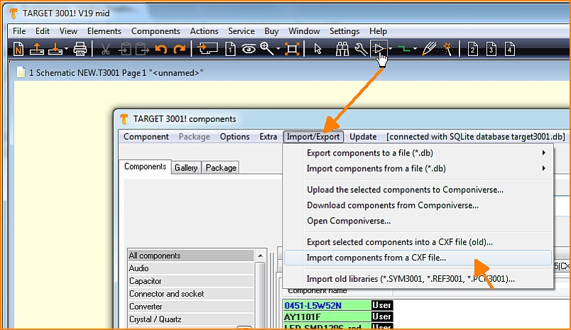
Image: Now open the component database in TARGET 3001! and import the data first as CXF.
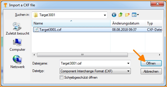
Image: Circuit diagram and solder foot pattern are transmitted through the CXF format.
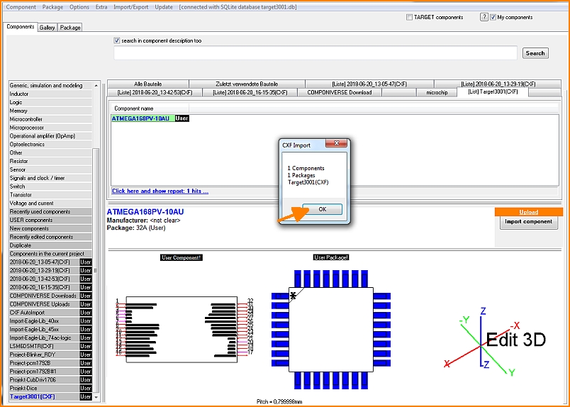
Image: That is how it prformss in TARGET 3001!
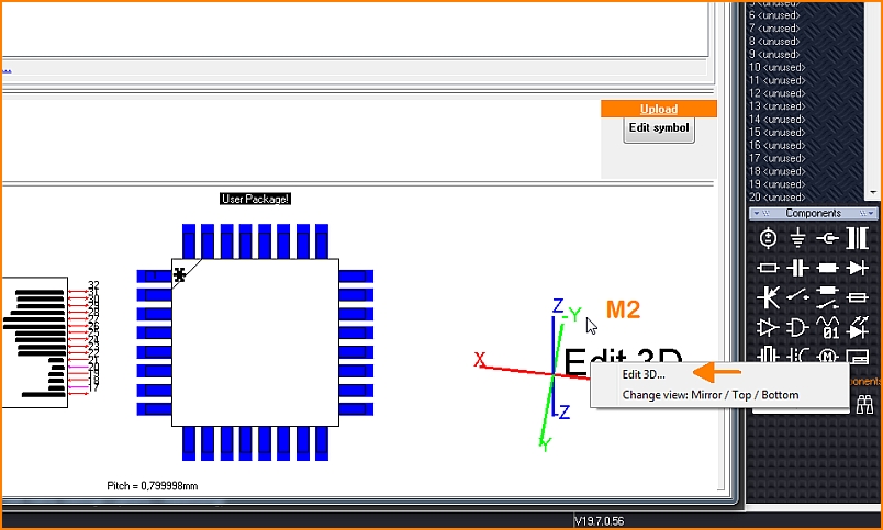
Image: To import the step model for the 3D view, click with the right mouse button on the coordinate system and select the "Edit 3D" option.
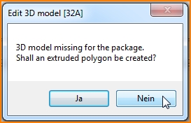
Image: An extruded polygon of the outline shall not be created, because we want to import a nice 3D model. So we choose "No" here. If a step file lacks, the representation of the component body as an extruded polygon is a fast alternative. The component contour is brought to height so that a cuboid or a cylinder or - depending on the contour - another body is created.
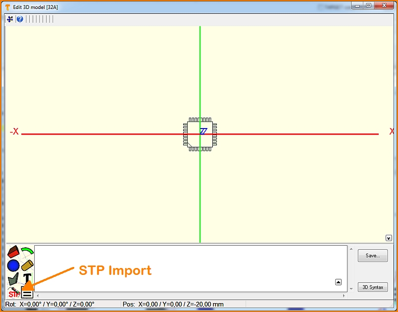
Image: Das landing pattern zeigt die Markierung im Südosten. Pad Nummer 1 wird also auf der horizontalen Reihe im Süden erwartet und zwar an Position links außen. Drücken Sie jetzt den Knopf zum Import einer Step-Datei.
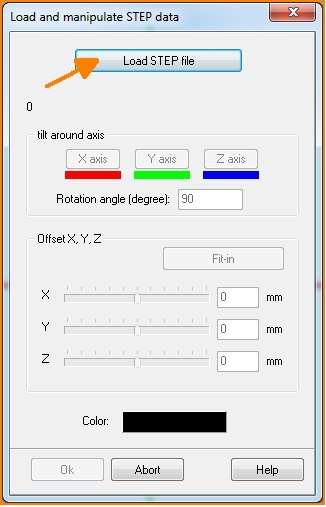
Image: Im sich öffnenden Dialog werden Sie aufgefordert das entsprechende file zu laden. Eventuell ist es erforderlich, das Modell auszurichten, denn nicht immer kommt das Objekt passgenau herein.
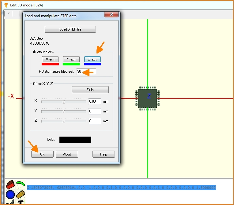
Image: Man kann also die 3D-AbImageung an den Koordinatenachsen drehen, oder verschieben, bis die AbImageung keinen Versatz mehr zeigt.
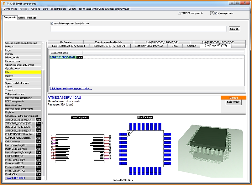
Image: Nach OK, schließen Sie alle Dialoge incl. der Datenbank. Ihr Bauteil befindet sich jetzt in der Datenbank und kann für Designs in TARGET verwendet werden.
en: Ultra Librarian

