GC-Prevue: Difference between revisions
| Line 6: | Line 6: | ||
you can approve the Gerber data you have created by TARGET 3001! in the sense of a CAM preview. | you can approve the Gerber data you have created by TARGET 3001! in the sense of a CAM preview. | ||
Downoad the latest version of GC-Prevue here: [http://www.graphicode.com/GC-Prevue http://www.graphicode.com/GC-Prevue] | Downoad the latest version of GC-Prevue here: [http://www.graphicode.com/GC-Prevue#download http://www.graphicode.com/GC-Prevue#download] | ||
== How to view Gerber data of a *.T3001 project with GC Prevue? == | == How to view Gerber data of a *.T3001 project with GC Prevue? == | ||
Revision as of 16:39, 10 August 2016
General
GC Prevue is a free Gerber viewer of GraphiCode http://www.graphicode.com
you can approve the Gerber data you have created by TARGET 3001! in the sense of a CAM preview.
Downoad the latest version of GC-Prevue here: http://www.graphicode.com/GC-Prevue#download
How to view Gerber data of a *.T3001 project with GC Prevue?
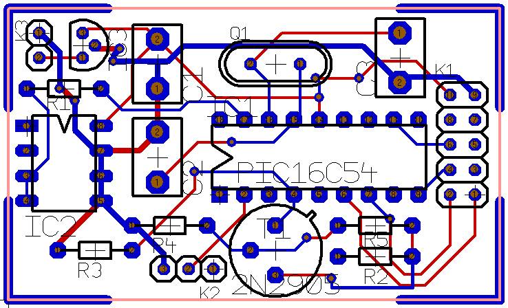
Image 1: TARGET 3001! Example project pic.T3001
Imagine your TARGET 3001! project was ready for production and you wouöd like to see how the gerberdata of your project would be interpreted by a PCB CAM system PCB houses use.
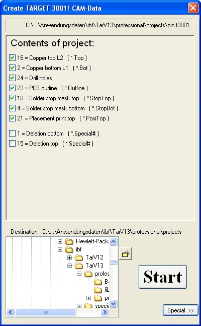
Image 2: Generate Gerberdata in TARGET 3001!
First generate the Gerber data from TARGET 3001! to a directory of your choice. Use the TARGET 3001! menu Input/Output formats/Production/(X-)Gerber and Drill output PCBout.
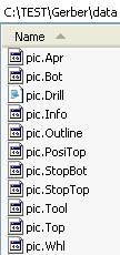
Image 3: Gerber data created to a directory of your choice
This directory now contains Gerber data. The file extensions have the following meaning:
*.Apr = aperture list
*.Bot = copper bottom
*.Drill = drill data
*.info = Info-Textfile
*.Outline = the board outline being milled
*.PosiTop = position print top
*.StopBot = solderstop bottom
*.StopTop = solderstop top
*.Tool = list of milling tools
*.Top = copper top
*.Whl = aperture list in Eagle format
Further files possible, depending on the performance of your project.
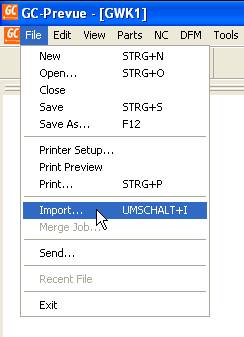
Image 4: Datenimport to GC Prevue
Now open in GC Prevue menü File/Import.
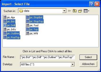
Image 5: Selection of relevant files
A browser opens, which allows selection of relevant files for import to GC Prevue.
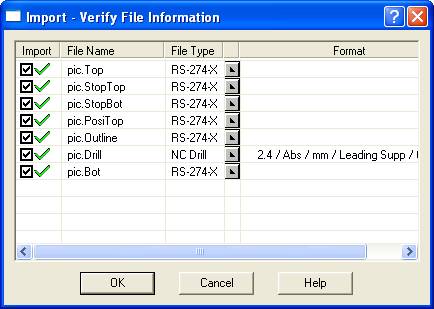
Image 6: Selection of relevant files in GC Prevue
How GC Prevue is going to interpret these files please see in this intermediate dialog (RS-274-X, XGerber resp. NCDrill, drill data). Press OK.
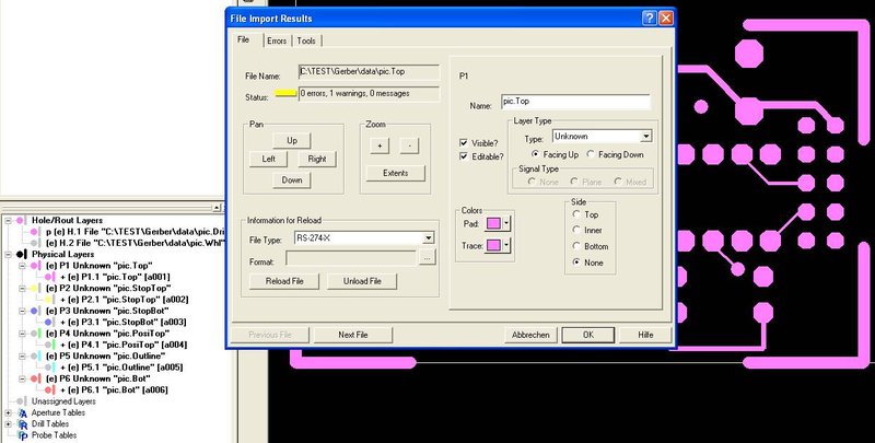
Image 7: View in GC Prevue according to it's default settings
GC Prevue now converts Gerberdata and shows the result according to it's default settings. Maybe you like it, maybe not. If not, you can colour each layer according to your preferences.
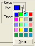
Image 8: Select a colour for each layer
It makes sense using the same layer colours like in TARGET 3001!. In our case blue for copper top.
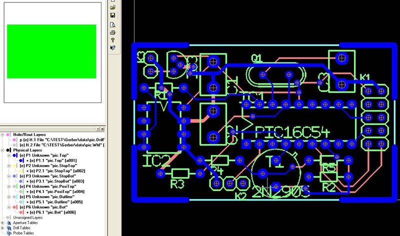
Image 9: pic.top e.g. in blue
See the result...
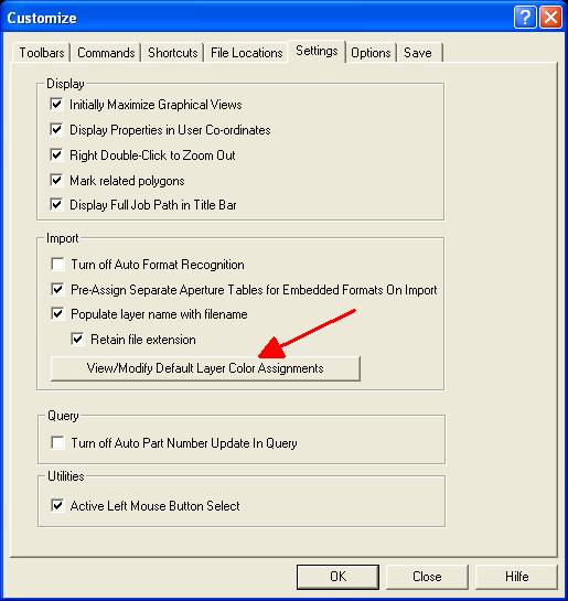
Image 10: Tools/Customize/Settings...
In case your image does not at all look like the one beside, please have a look in GC Prevue menu Tools/Customize/Settings. Check the entries...
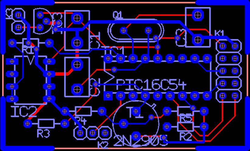
Image 11: pic.T3001 via Gerber in GC Prevue
... that's it. You can customize general settings in the dialog (see arrow) to predefine layer colours prior to import.
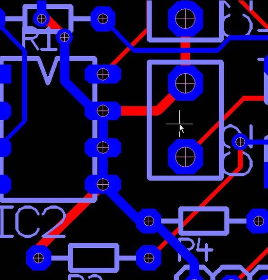
Image 12: A cutout from the project in GC Prevue
See that the the drills match exactly.
.
What must you do e.g. to reproduce your "gerberized" drill data with GC Prevue?
First generate the Gerbers in TARGET 3001! in dialog "File/Input/Output Formats/Production/(X-)Gerber and drill output PCBout..." :
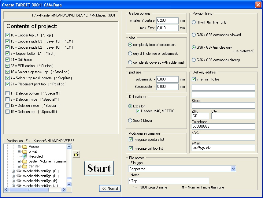
Image 1: Generate XGerber and Excellon data in TARGET 3001!
In GC-Prevue load the drill layout from the set of XGerber files by M2 on "Physical Layers" and then "Import":
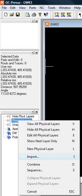
Image 2: Import XGerber data to GC Prevue
Load the drill data by a click M2 on "Hole/Rout Layers" and then "Import"
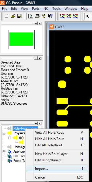
Image 3:Import drill
The file browser in GC-Prevue expects *.drl files so set it to "All Files". Now you load the drill data within the *.drill file. Drills and Layout match exactly:
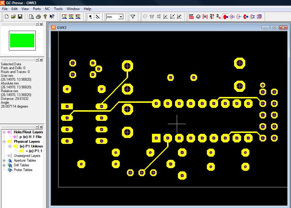
Image 4: Result
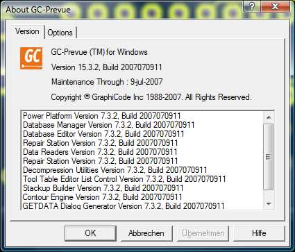
Image 5: Version used

