Differential Pairs: Difference between revisions
No edit summary |
No edit summary |
||
| Line 24: | Line 24: | ||
[[image:diffpairs9.png]]<br>Image: Now we place the tracks as a parallel running pair segment by segment. The track width and the track spacing are determined by the signal class in use, see above.<br><br><br> | [[image:diffpairs9.png]]<br>Image: Now we place the tracks as a parallel running pair segment by segment. The track width and the track spacing are determined by the signal class in use, see above.<br><br><br> | ||
[[image: | [[image:Diffpairs10_e.png]]<br>Image: A short distance in front of the connecting pads we cancel the action and give TARGET 3001! the command not to fulfill the connection automatically.<br><br><br> | ||
[[image:diffpairs11.png]]<br>Image: This is the way our differential Pair might look like.<br><br><br> | [[image:diffpairs11.png]]<br>Image: This is the way our differential Pair might look like.<br><br><br> | ||
Revision as of 09:04, 28 May 2014
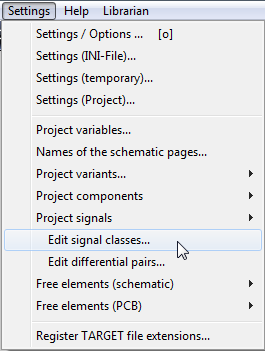
Image: The main menu "Settings"
In order to place differential pairs for Differential signaling it is clever to establish a signal class first. It is to determine minimum track width and minimum spacing between different signals. Later we will use this class for our differential pairs.
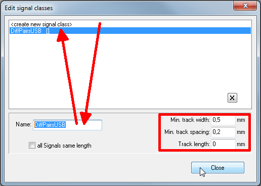
Image: The dialog "Edit signal classes"
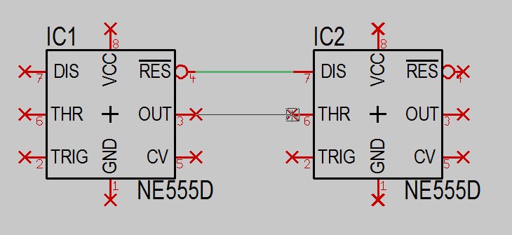
In our example we create the new signal class DiffPairsUSB with minimum values of 0,5mm und 0,2mm for track width and track spacing. After having imported two components to the schematic we change over to the mode Place wire [2] ![]() Now we press keyboard key [o] for Options. In the opening dialog we select our new net class (=signal class), so that the tracks in the layout later will achieve the properties which we have determined here.
Now we press keyboard key [o] for Options. In the opening dialog we select our new net class (=signal class), so that the tracks in the layout later will achieve the properties which we have determined here.
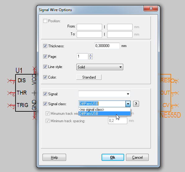
Image: The dialog Signal Wire Options
Now we connect the pins using the "Place wire [2]" mode.
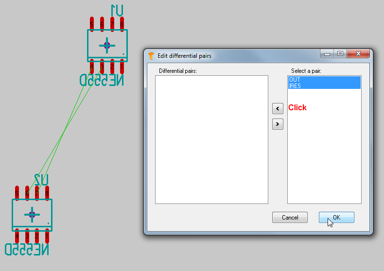
Image: Change to the layout view.
After having imported the packages to the layout we choose menu option: "Settings/Edit Differential Pairs". From the right we select the pair of signals we like to treat. Using the arrow in the center of the dialog we shift them to the left in order to activate them for differential signaling.
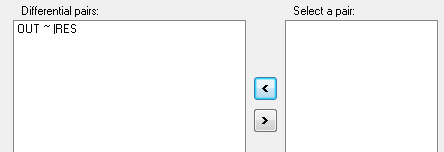
Image: The signals OUT and |RES are going to be differential pairs.
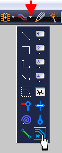
Image: Now use the extension of the icon "Draw track [2]" and select the button to "Draw a differential pair".
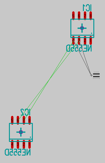
Image of the pointer in "Differential pair" - mode.
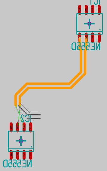
Image: Now we place the tracks as a parallel running pair segment by segment. The track width and the track spacing are determined by the signal class in use, see above.
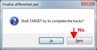
Image: A short distance in front of the connecting pads we cancel the action and give TARGET 3001! the command not to fulfill the connection automatically.
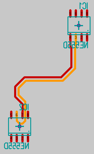
Image: This is the way our differential Pair might look like.


