Package Generator: Difference between revisions
| (69 intermediate revisions by 3 users not shown) | |||
| Line 1: | Line 1: | ||
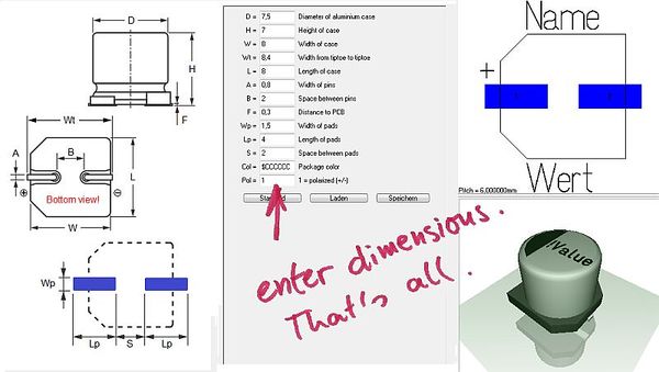
<big><b>Get footprint pattern and 3D model.</b></big><br><b>Select default from the list. Enter dimensions. Done.</b><br><br> | |||
<table border="0" cellpadding="20"><tr><td>[[Image:packagegenerator.jpg|600px]]</td></tr><tr><td><span class="plainlinks">[[Image:Videoicon_packagegenerator_144.jpg|link=//server.ibfriedrich.com/video/e/packagegenerator/packagegenerator.mp4|Video (3:28 Min)]]</span><br><br><big>'''Video (3:28 Min)'''</big></td></tr></table> | |||
== The Package generator dialog == | == The Package generator dialog == | ||
The "package generator" is made for easy creation of component packages including 3D view. It can be found in layout menu "Packages" and opens like this:<br><br> | The "package generator" is made for easy creation of component packages including 3D view. It can be found in layout menu "Packages" and opens like this:<br><br> | ||
[[Image:ghsgenerator_e.jpg| | [[Image:ghsgenerator_e.jpg|750px|The package generator dialog]]<br>Image: The package generator dialog<br><br><br> | ||
The dialog consists of four sections. Starting from the left: A list of various defaults to the left where you '''select your desired type''' of component. Right beside a technical drawing containing the definition of the parameters of the part. Such a drawing can be found in every data sheet. This image can not be modified here. Right beside the technical drawing you see the list of parameters, where all values according to the specifications of the data sheet can be entered. It is the basis for how the package later will look like. The abbreviations left of the equal sign are the same as in the technical drawing left of it. Up to the right the package image can be seen the way it appears in the layout later. Below the 3D image is shown.<br><br> | |||
Please select the default component type from the list top left: | |||
[[Image:ghsgenerator2_d.png|The list of component types]]<br>Image: The list of component types<br><br> | |||
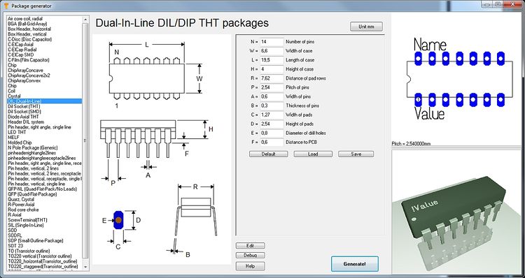
If you select a DIL (Dual-In-Line) from the list, the dialog changes the way that DIL parameters can be entered. | |||
[[Image:ghsgenerator3_e.jpg|750px|The dialog for a DIL]]<br>Image: The dialog for a DIL<br><br><br> | |||
[[Image: | The button '''Unit mm''' (top center) wants to make clear that there is no inch-scale here. The buttons '''Default''', '''Load''', '''Save''' in the center of the dialog refer to the set of values currently entered. One can save certain sets of values under an individual name and load them again. Or you might use the default setting. The button '''Generate!''' opens the well known dialog for saving the part to the data base. Component type, component name, package description and manufacturer can be entered as usual and the process is finished.<br><br> | ||
<br><br> | [[Image:Ghsgenerator4_e.jpg|Generate the desired package|none]]Image: Generate the desired package in order to save it under an individual name.<br><br> | ||
The more information you add to the dialog above, the better. You will find the package now in the range of designated package types by the particularly given name.<br><br> | |||
<br> | |||
== Quick creation of a package using the N-Pole type == | |||
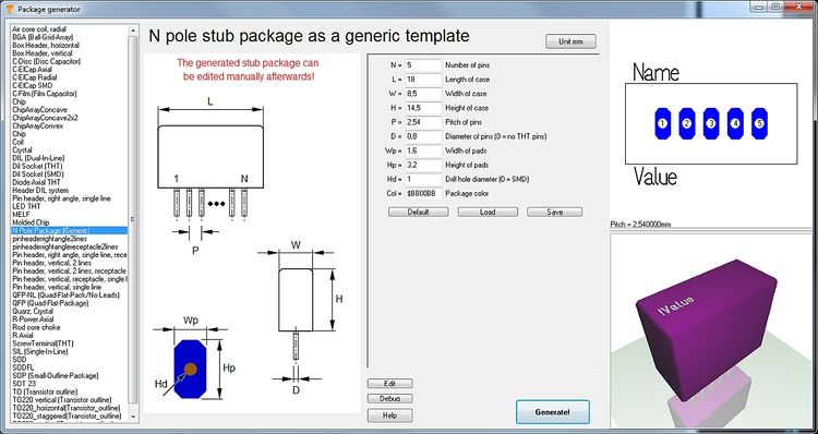
The package types in the list top left are based on a script. You can establish a new component type by saving a new script to a certain TARGET directory. If you are not a programmer and don't like to create a script on your own for a part which isn't represented here, you might use the package type N-Pole. Find it in the list:<br><br> | |||
[[Image:npole_e.jpg|750px|Package type N-Pole]]<br>Image:Package type N-Pole<br><br> | |||
The idea is simply to have a package outline with a certain kind and number of pads in a row. You can import this "raw blank" to a layout, finish it correctly there by pushing the pads on their correct place and save it again under a certain name. It might be the fact that the package won't come perfectly from the generator but the generator itself already has done a lot of constructive work. Now you might do corrections in the layout and save the part again. As you might know in the layout you can refine any part at any time and save it again (overwrite it or save it by a different name).<br><br><br> | |||
== | == How to create a package script == | ||
=== | === What is a package script? === | ||
Each component type which you will find in the list top left is based on exactly one script. So what you see in the dialog windoe when selecting a certain component type is defined by a script. A package script is a program which determins the geometrical shape of all drawing elements of a package. It is called script because it is stored as a text. So one does not create a script for one singular more or less complicated package but always for a package kind or type. A package type normally is built up according to special geometrical rules, only the number of leads (this is the easiest case) varies. View the script of package type by pressing the button: [[Image: button_edit.jpg]]<br><br> | |||
You can modify each script, save it under a different name ("Save as...") and then use it. When opening the package generator dialog again, the new script can be chosen from the list. | |||
Button: [[Image: button_debug.jpg]] opens the "Debugger" of the script.<br><br> | |||
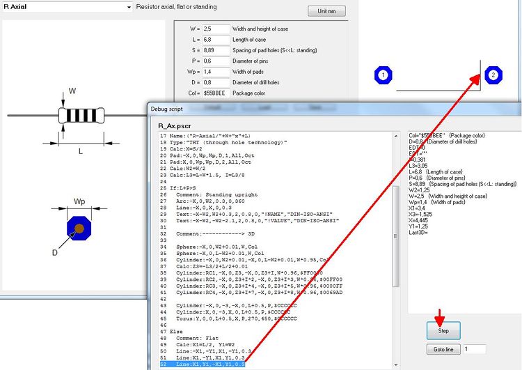
[[Image: debugdialog_e.jpg| | [[Image: debugdialog_e.jpg|750px|Debug dialog]]<br>Image: The Debug dialog<br><br> | ||
The "Step" button in the debug dialog allows a step by step (= row by row) walk through the script in order to see what each script row effects for the image(s). So if bugs in the script would occur, one can easily find them and fix them. In the above dialog for example row 52 is responsible for the vertical line on the right edge of the package outline. | |||
=== | === The setup of a script by an example === | ||
For the component type SIL (Single-In-Line) the script has the following look (syntax to the left, explanation to the right): | |||
{|border="1" cellspacing="1" cellpadding ="5" | {|border="1" cellspacing="1" cellpadding ="5" | ||
! | !Script syntax (line by line)!!Explanation | ||
|- | |- | ||
|01 Script:"SIL (Single-In-Line)"||Name | |01 Script:"SIL (Single-In-Line)"||Name of the script, shown in the selection box top left. Active with the next opening of the generator. | ||
|- | |- | ||
|02 Hint:"Single-In-Line SIL/SIP THT packages"|| | |02 Hint:"Single-In-Line SIL/SIP THT packages"||Hint which appears in the dialog right beside the selection box. | ||
|- | |- | ||
|03 Comment:"TARGET 3001! package script, Unit mm"|| | |03 Comment:"TARGET 3001! package script, Unit mm"||All following in this line is comment. | ||
|- | |- | ||
|04 Author:" | |04 Author:"Steve Miller"||Author of the script. | ||
|- | |- | ||
|05 Date:"28.11.2013"|| | |05 Date:"28.11.2013"||Date of last modification. Needs to be controled/managed manually. | ||
|- | |- | ||
|06 Image:"SIL.png"|| | |06 Image:"SIL.png"||File name of the image shown to the left. PNG-Image always 350x580 pixel. | ||
|- | |- | ||
|07 Num:N,7,"Number of pins",Edt|| | |07 Num:N,7,"Number of pins",Edt||Declare numeric variable. Here the input box "Number of pins" is defined. Name, Default value, Hint, Display. Display missing=not shown, EDT=editable, RDO=Read-Only. Variable names need to start with one or more alphabetic character. Then numeric characters may follow. Upper case/lower case is not recignized. | ||
|- | |- | ||
|08 Num:W,2.5,"Width of case",Edt||dito. | |08 Num:W,2.5,"Width of case",Edt||dito. Input box "Width of case" is defined. | ||
|- | |- | ||
|09 Num:L,18,"Length of case",Edt||dito. | |09 Num:L,18,"Length of case",Edt||dito. Input box "Length of case" is defined. | ||
|- | |- | ||
|10 Num:H,5.1,"Height of case",Edt||dito. | |10 Num:H,5.1,"Height of case",Edt||dito. Input box "Height of case" is defined. | ||
|- | |- | ||
|11 Num:P,2.54,"Pitch of pins",Edt||dito. | |11 Num:P,2.54,"Pitch of pins",Edt||dito. Input box "Pitch of pins" is defined. | ||
|- | |- | ||
|12 Num:A,0.6,"Width or radius of pins",Edt||dito. | |12 Num:A,0.6,"Width or radius of pins",Edt||dito. Input box "Width or radius of pins" is defined. | ||
|- | |- | ||
|13 Num:B,0.3,"Thickness of pins or zero",Edt||dito. | |13 Num:B,0.3,"Thickness of pins or zero",Edt||dito. Input box "Thickness of pins or zero" is defined. | ||
|- | |- | ||
|14 Num:C,1.5,"Width of pads",Edt||dito. | |14 Num:C,1.5,"Width of pads",Edt||dito. Input box "Width of pads" is defined. | ||
|- | |- | ||
|15 Num:D,2.5,"Height of pads",Edt||dito. | |15 Num:D,2.5,"Height of pads",Edt||dito. Input box "Height of pads" is defined. | ||
|- | |- | ||
|16 Num:E,0.9,"Diameter of drill holes",Edt||dito. | |16 Num:E,0.9,"Diameter of drill holes",Edt||dito. Input box "Diameter of drill holes" is defined. | ||
|- | |- | ||
|17 Num:F,0.1,"Distance to PCB",Edt||dito. | |17 Num:F,0.1,"Distance to PCB",Edt||dito. Input box "Distance to PCB" is defined. | ||
|- | |- | ||
|18 Str:Col,"$225522","Package color",Edt|| | |18 Str:Col,"$225522","Package color",Edt||Declare text variable. Name, Default value, Hint, Display. Display missing=not shown, EDT=editable, RDO=Read-Only. Colors need to be defined hexadecimally like $BBGGRR . The two B represent Blue, the two G represent Green and the two R represent Red. | ||
|- | |- | ||
|19 <br>|| | |19 <br>||Blank line | ||
|- | |- | ||
|20 Comment:------------> Drawing<br>|| | |20 Comment:------------> Drawing<br>||Comment: The syntax of the package (land pattern with package outline) starts from here. | ||
|- | |- | ||
|21 <br>|| | |21 <br>||Blank line | ||
|- | |- | ||
|22 Name:("SIL-"+N+"/"+L+"x"+W+"x"+H)<br>|| | |22 Name:("SIL-"+N+"/"+L+"x"+W+"x"+H)<br>||This is how the proposal for a package name is created when pushing the "Generate" button. It is a string. The visible is denoted within quotes. Those characters added by a plus sign are variables. | ||
|- | |- | ||
|23 Type:"SIL / SIP (single in-line package)"<br>|| | |23 Type:"SIL / SIP (single in-line package)"<br>||Package type. Please inherit from data base "package types". | ||
|- | |- | ||
|24 Calc:X1=(N/2-0.5)*P<br>|| | |24 Calc:X1=(N/2-0.5)*P<br>||Announce a calculation. Variable=Expression. More than one calculation separate by comma. Operators within the expression: <nowiki>+, -, *, /, ()</nowiki>, mathematic functions, see below. | ||
|- | |- | ||
|25 For:I,1,N<br>||For- | |25 For:I,1,N<br>||Begin a For-loop. Hereby iteratively is executed what line 26 defines: Variable name, Start value, End value, (step=1). Start value and End value can be expressions. | ||
|- | |- | ||
|26 | |26 Pad:-X1+P*(I-1),0,C,D,E,I,All,Oct<br>||Create a pad in the layout. X, Y, Width, Height, Drill diameter, Padnumber, Layer, Form, Rotation, (Padname=''), (Solder paste=True), (Solder stop=True). | ||
|- | |- | ||
|27 EndFor<br>||Ende | |27 EndFor<br>||Ende of the For loop. For loops can be nested. Colon optionally. | ||
|- | |- | ||
|28 Calc:X=L/2<br>|| | |28 Calc:X=L/2<br>||Announce a calculation. Variable=Expression. More than on calculation separate by comma. Operators within the expression: <nowiki>+, -, *, /, ()</nowiki>, mathematic functions, see below. | ||
|- | |- | ||
|29 Calc:Y=W/2<br>|| | |29 Calc:Y=W/2<br>||Announce a calculation. Variable=Expression. More than on calculation separate by comma. Operators within the expression: <nowiki>+, -, *, /, ()</nowiki>, mathematic functions, see below. | ||
|- | |- | ||
|30 Line:-X,-Y,X,-Y,0.3<br>|| | |30 Line:-X,-Y,X,-Y,0.3<br>||Draw a line in the layout. X1, Y1, X2, Y2, (Line width=0.3), (Layer Function=4=Position top). | ||
* | *Layer function: 3=Position bottom, 4=Position top, 12=Solder stop top, 15=Solder paste top, 17=Gold top, 19=Glue top | ||
|- | |- | ||
|31 Line:X,-Y,X,Y,0.3<br>|| | |31 Line:X,-Y,X,Y,0.3<br>||Draw a line in the layout. X1, Y1, X2, Y2, (Line width=0.3), (Layer Function=4=Position top). | ||
* | *Layer function: 3=Position bottom, 4=Position top, 12=Solder stop top, 15=Solder paste top, 17=Gold top, 19=Glue top | ||
|- | |- | ||
|32 Line:X,Y,-X,Y,0.3<br>|| | |32 Line:X,Y,-X,Y,0.3<br>||Draw a line in the layout. X1, Y1, X2, Y2, (Line width=0.3), (Layer Function=4=Position top). | ||
* | *Layer function: 3=Position bottom, 4=Position top, 12=Solder stop top, 15=Solder paste top, 17=Gold top, 19=Glue top | ||
|- | |- | ||
|33 Line:-X,Y,-X,-Y,0.3<br>|| | |33 Line:-X,Y,-X,-Y,0.3<br>||Draw a line in the layout. X1, Y1, X2, Y2, (Line width=0.3), (Layer Function=4=Position top). | ||
* | *Layer function: 3=Position bottom, 4=Position top, 12=Solder stop top, 15=Solder paste top, 17=Gold top, 19=Glue top | ||
|- | |- | ||
|34 Calc:X=X1-P/2<br>|| | |34 Calc:X=X1-P/2<br>||Announce a calculation. Variable=Expression. More than on calculation separate by comma. Operators within the expression: <nowiki>+, -, *, /, ()</nowiki>, mathematic functions, see below. | ||
|- | |- | ||
|35 Line:-X,Y,-X,-Y,0.3<br>|| | |35 Line:-X,Y,-X,-Y,0.3<br>||Draw a line in the layout. X1, Y1, X2, Y2, (Line width=0.3), (Layer Function=4=Position top). | ||
* | *Layer function: 3=Position bottom, 4=Position top, 12=Solder stop top, 15=Solder paste top, 17=Gold top, 19=Glue top | ||
|- | |- | ||
|36 Text:-X+1.5,W/2+1,2.5,1.6,0,"!Name","DIN-ISO-ANSI"<br>|| | |36 Text:-X+1.5,W/2+1,2.5,1.6,0,"!Name","DIN-ISO-ANSI"<br>||Display text in the layout. X, Y, Hight, Width, Rotation, Text content, Charcter set, (Layer function=4=Position top). | ||
|- | |- | ||
|37 Text:-X+1.5,-W/2-3.2,2.5,1.6,0,"!Value","DIN-ISO-ANSI"<br>|| | |37 Text:-X+1.5,-W/2-3.2,2.5,1.6,0,"!Value","DIN-ISO-ANSI"<br>||Display text in the layout. X, Y, Hight, Width, Rotation, Text content, Charcter set, (Layer function=4=Position top). | ||
|- | |- | ||
|38 Comment:------------> 3D<br>|| | |38 Comment:------------> 3D<br>||Comment: The syntax of the 3D image starts from here. | ||
|- | |- | ||
|39 Solid:0,0,F,0,0,F+H,L,W,Col,0.4<br>|| | |39 Solid:0,0,F,0,0,F+H,L,W,Col,0.4<br>||Display a cuboid in 3D. X1, Y1, Z1, X2, Y2, Z2, Width, Height, Color, (Champfer radius=0). The [[3D_Syntax|Syntax for the 3D modelling]] applies. | ||
|- | |- | ||
|40 Text3D:-X1+1.5,-0.5,F+H+0.01,1.2,0.5,0,"DIN-ISO-ANSI","!Value",$FFFFFF<br>|| | |40 Text3D:-X1+1.5,-0.5,F+H+0.01,1.2,0.5,0,"DIN-ISO-ANSI","!Value",$FFFFFF<br>||Display text in the 3D image. X1, Y1, Z1, Height, Width, Rotation, Character set, Text content, Color. The [[3D_Syntax|Syntax for the 3D modelling]] applies. | ||
|- | |- | ||
|41 Cylinder:-X1,0,F+H-0.1,-X1,0,F+H+0.01,1,$FFFFFF<br>|| | |41 Cylinder:-X1,0,F+H-0.1,-X1,0,F+H+0.01,1,$FFFFFF<br>||Display cylinder in 3D. X1, Y1, Z1, X2, Y2, Z2, Diameter, Color, (Champfer radius=0). The [[3D_Syntax|Syntax for the 3D modelling]] applies. | ||
|- | |- | ||
|42 For:I,1,N<br>|| For | |42 For:I,1,N<br>|| For loop in order to create the 3D leads iteratively | ||
|- | |- | ||
|43 Calc:X2=-X1+P*(I-1),Y2=0,Z=(F+H)/2<br>|| | |43 Calc:X2=-X1+P*(I-1),Y2=0,Z=(F+H)/2<br>||Announcement of a calculation | ||
|- | |- | ||
|44 IF:B>0<br>||If | |44 IF:B>0<br>||Start If condition. Expression Operator Expression. Operators: =, <, >, <=, >=. Combine several conditions by & (=and). | ||
|- | |- | ||
|45 Solid:X2,Y2,-3,X2,Y2,0.1,A,B,$CCCCCC,0<br>|| | |45 Solid:X2,Y2,-3,X2,Y2,0.1,A,B,$CCCCCC,0<br>||Display a cuboid in 3D. X1, Y1, Z1, X2, Y2, Z2, Width, Height, Color, (Champfer radius=0). The [[3D_Syntax|Syntax for the 3D modelling]] applies. | ||
|- | |- | ||
|46 ELSE<br>||Else | |46 ELSE<br>||Else branch. Colon optional. | ||
|- | |- | ||
|47 Cylinder:X2,Y2,-3,X2,Y2,0.1,A,$CCCCCC<br>|| | |47 Cylinder:X2,Y2,-3,X2,Y2,0.1,A,$CCCCCC<br>||Display cylinder in 3D. X1, Y1, Z1, X2, Y2, Z2, Diameter, Color, (Champfer radius=0). The [[3D_Syntax|Syntax for the 3D modelling]] applies. | ||
|- | |- | ||
|48 ENDIF<br>|| | |48 ENDIF<br>||End of the If condition. If conditions can be nested. Colon optional. | ||
|- | |- | ||
|49 EndFor|| | |49 EndFor||End of the For loop. For loops can be nested as well. Colon optional. | ||
|} | |} | ||
<br><br> | <br><br> | ||
''' | '''Please note:''' The values of the variables for the current SIL package are denoted on the right hand side of the debugger dialog.<br><br> | ||
=== Script commands === | |||
==== General ==== | |||
Every '''textual indication''' (=string) is embedded in quotes. Example: "Hello".<br> | |||
'''Coordinate indications''' are in metric scale [mm]. If you look on the X-Y-plane, the positive Z-axis points upward to the spectator.<br> | |||
'''Numeric characters''' are rounded to 1/1000.<br> | |||
'''Angle indications''' are in 0...360 degrees [°].<br> | |||
The '''rotational direction''' is CCW (=CounterClockWise). 0° is east. | |||
The '''right-hand-rule''' applies for all axes.<br> | |||
'''Colors''' are indicated hexadecimally according to $BBGGRR. B represents Blue, G represents Green and R represents Red.<br><br> | |||
==== Script | ==== Script commands in detail ==== | ||
The following script commands currently exist: | |||
*SCRIPT: Name | *SCRIPT: Name of the script, shown in the selection box top left. Active with the next opening of the generator. | ||
*HINT: | *HINT: Hint which appears in the dialog right beside the selection box. | ||
*COMMENT: | *COMMENT: All following in this line is comment. | ||
*AUTHOR: | *AUTHOR: Author of the script. | ||
*DATE: | *DATE: Date of last modification. Needs to be controled/managed manually. | ||
*IMAGE: | *IMAGE: File name of the image shown to the left. PNG-Image always 350x580 pixel. | ||
*TYPE: | *TYPE: Package type. Please inherit from data base "package types". | ||
*NAME: | *NAME: This is how the proposal for a package name is created when pushing the "Generate" button. It is a string. The visible is denoted within quotes. Those characters added by a plus sign are variables. | ||
*NUM: | *NUM: Declare numeric variable. Here the input box "Number of pins" is defined. Name, Default value, Hint, Display. Display missing=not shown, EDT=editable, RDO=Read-Only. Variable names need to start with one or more alphabetic character. Then numeric characters may follow. Upper case/lower case is not recognized. | ||
*STR: | *STR: Declare text variable. Name, Default value, Hint, Display. Display missing=not shown, EDT=editable, RDO=Read-Only. | ||
*CALC: | *CALC: Announce a calculation. Variable=Expression. More than on calculation separate by comma. Operators within the expression: <nowiki>+, -, *, /, (),</nowiki> mathematic functions: | ||
**ABS(x) | **ABS(x) Absolute, | ||
**SIN(x) Sinus [°], | **SIN(x) Sinus [°], | ||
**ASIN(x) Arcus Sinus, | **ASIN(x) Arcus Sinus, | ||
| Line 180: | Line 198: | ||
**TAN(x) Tangens, | **TAN(x) Tangens, | ||
**ATAN(x) Arcus Tangens, | **ATAN(x) Arcus Tangens, | ||
**MAX(x,y) | **MAX(x,y) Major value of the expressions x and y, | ||
**MIN(x,y) | **MIN(x,y) Minor value of the expressions x and y, | ||
**INT(x) | **INT(x) Integer, rounded, | ||
**SQR(x) | **SQR(x) Square, | ||
**SQRT(x) | **SQRT(x) Square root, | ||
**EVEN(x) 1 | **EVEN(x) 1 if even, 0 if uneven, | ||
**ODD(x) 1 | **ODD(x) 1 if uneven, 0 if even. | ||
** | **Calculations for strings only know the operator + for appending and the following functions: | ||
**NCH(i) Number-Character: 1=A, 2=B, ... 21=Z, 22=AA, 23=AB, ... 42=AZ, 43=BA ... ( | **NCH(i) Number-Character: 1=A, 2=B, ... 20=Y, 21=AA, 22=AB, ... 40=AY, 41=BA ... (e.g. for the line naming of BGA packages, without I,O,Q,S,X and Z) | ||
**CHR(i) ASCII- | **NCZ(i) Number-Character: 1=A, 2=B, ... 21=Z, 22=AA, 23=AB, ... 42=AZ, 43=BA ... (e.g. for the line naming of BGA packages, without I,O,Q,S,X but with Z) | ||
**INT(i) | **CHR(i) ASCII-Characters: 33=!, ... 65=A, 66=B, ... 90=Z, ... 97=a, 98=b, ... 122=z, ... 219=? | ||
**REAL(i) | **INT(i) Integer, rounded, | ||
**REAL(i) Decimal character with 3 digits after the decimal point | |||
*FOR: For | *FOR: Begin a For loop. Hereby iteratively is executed what line 26 defines: Variable name, Start value, End value, (step=1). Start value and End value can be expressions. | ||
*ENDFOR: | *ENDFOR:End of the For loop. For loops can be nested. Colon optionally. | ||
*IF: If | *IF: Start If condition. Expression Operator Expression. Operators: =, <, >, <=, >=. Combine several conditions by & (=and), | (=or). | ||
*ELSE: Else | *ELSE: Else branch. Colon optional. | ||
*ENDIF: | *ENDIF: End of the If condition. If conditions can be nested. Colon optional. | ||
*PAD: Pad | *PAD: Create a Pad in the layout view. X, Y, Width, Height, Drill diameter, Padnumber, Layer, Form, Rotation, (Padname=''), (Solderpaste=True), (Solderstopp=True). | ||
** | **Layer = Top or Bot or All | ||
**Form = Rnd | **Form = Rnd or Oct or Rct or Ovl | ||
** | **Solder paste = True or False | ||
** | **Solder stopp = True or False | ||
** | **Specifications in brackets are optional. Default is going to be used. | ||
*LINE: | *LINE: Draw a line in the layout. X1, Y1, X2, Y2, (Line width=0.3), (Layer Function=4=Position top). | ||
** | **Layer function: 3=Position bottom, 4=Position top, 12=Solder stop top, 15=Solder paste top, 17=Gold top, 19=Glue top | ||
*ARC: | *ARC: Draw an arc in the layout. X, Y, Radius, Line width, Start angle, End angle, (Layer function=4=Position top). | ||
*CIRC: | *CIRC: Draw a circle in the layout. X, Y, Radius, (Layer function=4=Position top). | ||
*TRI: | *TRI: Draw a triangle in the layout. X1, Y1, X2, Y2, X3, Y3, (Layer function=4=Position top). | ||
*RECT: | *RECT: Draw a rectangle in the layout. X, Y, Width, Height, Rotation, (Layer function=4=Position top). | ||
*TEXT: | *TEXT: Display text in the layout. X, Y, Hight, Width, Rotation, Text content, Character set, (Layer function=4=Position top). | ||
**!NAME | **!NAME and !VALUE as Text content are later swapped by name and value of the real component. | ||
** | **Character set= TARGET or DIN-ISO-ANSI or Arial or Times New Roman ... | ||
*SOLID: | *SOLID: Display a cuboid in 3D. X1, Y1, Z1, X2, Y2, Z2, Width, Height, Color, (Champfer radius=0). | ||
*CYLINDER: | *CYLINDER: Display cylinder in 3D. X1, Y1, Z1, X2, Y2, Z2, Diameter, Color, (Champfer radius=0). | ||
*TORUS: | *TORUS: Display arc in 3D. X or Y or Z, Xm, Ym, Zm, Radius, Diameter, Start angle, End angle, Color. | ||
*SPHERE: | *SPHERE: Display a ball in 3D. Xm, Ym, Zm, Diameter, Color. | ||
*POLYGON3D: | *POLYGON3D: Display a polygon being extruded to Z-direction. N, X1, Y1, X2, Y2, ... Xn, Yn, Z1, dZ, Color. | ||
*TEXT3D: | *TEXT3D: Display text in 3D. X1, Y1, Z1, Hight, Width, Rotation, Character set, Text content, Color. | ||
*3D: | *3D: Create any line for 3D display. | ||
*EXIT: | *EXIT: Quit program immediately. | ||
If an array has e. g. n=16 poles, it needs to have Pad 1 below and Pad 8=n/2 and a row from Pad 2 to Pad 7=n/2-1.<br> | |||
Above one needs Pad 9=n/2+1 and Pad 16=n. Inbetween one needs the row from Pad 10=n/2+2 to Pad 15=n-1.<br> | |||
In 3D one needs a left and a right endcap and n-4)/2 intermediate pieces.<br><br><br> | |||
=== | === Save and activate a script === | ||
A script is activated modified and saved in the Edit-Dialog. Directory of storage is: | |||
''' | '''User\Name\AppData\Roaming\ibf\TarVxx\<Edition>\PCK_gen''' | ||
To this place also the *.png image is saved which contains the technical drawing of the part in question. This image appears in the dialog to the left. It makes sense giving them the same file name like the script has (not a must).<br><br> | |||
=== | === Delete a script from the list === | ||
Simply delete it from this directory:<br> | |||
''' | '''User\Name\AppData\Roaming\ibf\TarVxx\<edition>\PCK_gen'''<br> | ||
With the next opening of the dialog it will be vanished from the list.<br> | |||
<br><br> | <br><br> | ||
<br><br> | <br><br> | ||
[mailto:target@ibfriedrich.com?Subject= | [mailto:target@ibfriedrich.com?Subject=Package_Generator I have a question here] | ||
<br><br><br> | <br><br><br> | ||
[[de: Gehäuse-Generator]][[fr: Générateur de boîtier]] | [[de: Gehäuse-Generator]][[fr: Générateur de boîtier]][[category:homepage]] | ||
Latest revision as of 08:20, 11 September 2018
Get footprint pattern and 3D model.
Select default from the list. Enter dimensions. Done.
 |
Video (3:28 Min) |
The Package generator dialog
The "package generator" is made for easy creation of component packages including 3D view. It can be found in layout menu "Packages" and opens like this:
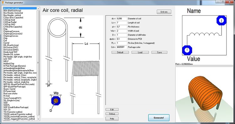
Image: The package generator dialog
The dialog consists of four sections. Starting from the left: A list of various defaults to the left where you select your desired type of component. Right beside a technical drawing containing the definition of the parameters of the part. Such a drawing can be found in every data sheet. This image can not be modified here. Right beside the technical drawing you see the list of parameters, where all values according to the specifications of the data sheet can be entered. It is the basis for how the package later will look like. The abbreviations left of the equal sign are the same as in the technical drawing left of it. Up to the right the package image can be seen the way it appears in the layout later. Below the 3D image is shown.
Please select the default component type from the list top left:
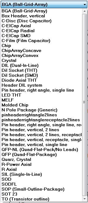
Image: The list of component types
If you select a DIL (Dual-In-Line) from the list, the dialog changes the way that DIL parameters can be entered.
The button Unit mm (top center) wants to make clear that there is no inch-scale here. The buttons Default, Load, Save in the center of the dialog refer to the set of values currently entered. One can save certain sets of values under an individual name and load them again. Or you might use the default setting. The button Generate! opens the well known dialog for saving the part to the data base. Component type, component name, package description and manufacturer can be entered as usual and the process is finished.
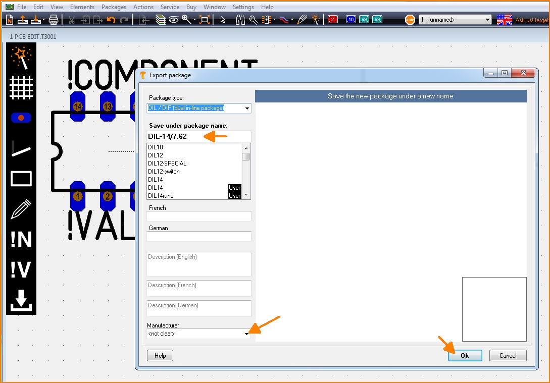
Image: Generate the desired package in order to save it under an individual name.
The more information you add to the dialog above, the better. You will find the package now in the range of designated package types by the particularly given name.
Quick creation of a package using the N-Pole type
The package types in the list top left are based on a script. You can establish a new component type by saving a new script to a certain TARGET directory. If you are not a programmer and don't like to create a script on your own for a part which isn't represented here, you might use the package type N-Pole. Find it in the list:
The idea is simply to have a package outline with a certain kind and number of pads in a row. You can import this "raw blank" to a layout, finish it correctly there by pushing the pads on their correct place and save it again under a certain name. It might be the fact that the package won't come perfectly from the generator but the generator itself already has done a lot of constructive work. Now you might do corrections in the layout and save the part again. As you might know in the layout you can refine any part at any time and save it again (overwrite it or save it by a different name).
How to create a package script
What is a package script?
Each component type which you will find in the list top left is based on exactly one script. So what you see in the dialog windoe when selecting a certain component type is defined by a script. A package script is a program which determins the geometrical shape of all drawing elements of a package. It is called script because it is stored as a text. So one does not create a script for one singular more or less complicated package but always for a package kind or type. A package type normally is built up according to special geometrical rules, only the number of leads (this is the easiest case) varies. View the script of package type by pressing the button: ![]()
You can modify each script, save it under a different name ("Save as...") and then use it. When opening the package generator dialog again, the new script can be chosen from the list.
Button: ![]() opens the "Debugger" of the script.
opens the "Debugger" of the script.
The "Step" button in the debug dialog allows a step by step (= row by row) walk through the script in order to see what each script row effects for the image(s). So if bugs in the script would occur, one can easily find them and fix them. In the above dialog for example row 52 is responsible for the vertical line on the right edge of the package outline.
The setup of a script by an example
For the component type SIL (Single-In-Line) the script has the following look (syntax to the left, explanation to the right):
| Script syntax (line by line) | Explanation |
|---|---|
| 01 Script:"SIL (Single-In-Line)" | Name of the script, shown in the selection box top left. Active with the next opening of the generator. |
| 02 Hint:"Single-In-Line SIL/SIP THT packages" | Hint which appears in the dialog right beside the selection box. |
| 03 Comment:"TARGET 3001! package script, Unit mm" | All following in this line is comment. |
| 04 Author:"Steve Miller" | Author of the script. |
| 05 Date:"28.11.2013" | Date of last modification. Needs to be controled/managed manually. |
| 06 Image:"SIL.png" | File name of the image shown to the left. PNG-Image always 350x580 pixel. |
| 07 Num:N,7,"Number of pins",Edt | Declare numeric variable. Here the input box "Number of pins" is defined. Name, Default value, Hint, Display. Display missing=not shown, EDT=editable, RDO=Read-Only. Variable names need to start with one or more alphabetic character. Then numeric characters may follow. Upper case/lower case is not recignized. |
| 08 Num:W,2.5,"Width of case",Edt | dito. Input box "Width of case" is defined. |
| 09 Num:L,18,"Length of case",Edt | dito. Input box "Length of case" is defined. |
| 10 Num:H,5.1,"Height of case",Edt | dito. Input box "Height of case" is defined. |
| 11 Num:P,2.54,"Pitch of pins",Edt | dito. Input box "Pitch of pins" is defined. |
| 12 Num:A,0.6,"Width or radius of pins",Edt | dito. Input box "Width or radius of pins" is defined. |
| 13 Num:B,0.3,"Thickness of pins or zero",Edt | dito. Input box "Thickness of pins or zero" is defined. |
| 14 Num:C,1.5,"Width of pads",Edt | dito. Input box "Width of pads" is defined. |
| 15 Num:D,2.5,"Height of pads",Edt | dito. Input box "Height of pads" is defined. |
| 16 Num:E,0.9,"Diameter of drill holes",Edt | dito. Input box "Diameter of drill holes" is defined. |
| 17 Num:F,0.1,"Distance to PCB",Edt | dito. Input box "Distance to PCB" is defined. |
| 18 Str:Col,"$225522","Package color",Edt | Declare text variable. Name, Default value, Hint, Display. Display missing=not shown, EDT=editable, RDO=Read-Only. Colors need to be defined hexadecimally like $BBGGRR . The two B represent Blue, the two G represent Green and the two R represent Red. |
| 19 |
Blank line |
| 20 Comment:------------> Drawing |
Comment: The syntax of the package (land pattern with package outline) starts from here. |
| 21 |
Blank line |
| 22 Name:("SIL-"+N+"/"+L+"x"+W+"x"+H) |
This is how the proposal for a package name is created when pushing the "Generate" button. It is a string. The visible is denoted within quotes. Those characters added by a plus sign are variables. |
| 23 Type:"SIL / SIP (single in-line package)" |
Package type. Please inherit from data base "package types". |
| 24 Calc:X1=(N/2-0.5)*P |
Announce a calculation. Variable=Expression. More than one calculation separate by comma. Operators within the expression: +, -, *, /, (), mathematic functions, see below. |
| 25 For:I,1,N |
Begin a For-loop. Hereby iteratively is executed what line 26 defines: Variable name, Start value, End value, (step=1). Start value and End value can be expressions. |
| 26 Pad:-X1+P*(I-1),0,C,D,E,I,All,Oct |
Create a pad in the layout. X, Y, Width, Height, Drill diameter, Padnumber, Layer, Form, Rotation, (Padname=), (Solder paste=True), (Solder stop=True). |
| 27 EndFor |
Ende of the For loop. For loops can be nested. Colon optionally. |
| 28 Calc:X=L/2 |
Announce a calculation. Variable=Expression. More than on calculation separate by comma. Operators within the expression: +, -, *, /, (), mathematic functions, see below. |
| 29 Calc:Y=W/2 |
Announce a calculation. Variable=Expression. More than on calculation separate by comma. Operators within the expression: +, -, *, /, (), mathematic functions, see below. |
| 30 Line:-X,-Y,X,-Y,0.3 |
Draw a line in the layout. X1, Y1, X2, Y2, (Line width=0.3), (Layer Function=4=Position top).
|
| 31 Line:X,-Y,X,Y,0.3 |
Draw a line in the layout. X1, Y1, X2, Y2, (Line width=0.3), (Layer Function=4=Position top).
|
| 32 Line:X,Y,-X,Y,0.3 |
Draw a line in the layout. X1, Y1, X2, Y2, (Line width=0.3), (Layer Function=4=Position top).
|
| 33 Line:-X,Y,-X,-Y,0.3 |
Draw a line in the layout. X1, Y1, X2, Y2, (Line width=0.3), (Layer Function=4=Position top).
|
| 34 Calc:X=X1-P/2 |
Announce a calculation. Variable=Expression. More than on calculation separate by comma. Operators within the expression: +, -, *, /, (), mathematic functions, see below. |
| 35 Line:-X,Y,-X,-Y,0.3 |
Draw a line in the layout. X1, Y1, X2, Y2, (Line width=0.3), (Layer Function=4=Position top).
|
| 36 Text:-X+1.5,W/2+1,2.5,1.6,0,"!Name","DIN-ISO-ANSI" |
Display text in the layout. X, Y, Hight, Width, Rotation, Text content, Charcter set, (Layer function=4=Position top). |
| 37 Text:-X+1.5,-W/2-3.2,2.5,1.6,0,"!Value","DIN-ISO-ANSI" |
Display text in the layout. X, Y, Hight, Width, Rotation, Text content, Charcter set, (Layer function=4=Position top). |
| 38 Comment:------------> 3D |
Comment: The syntax of the 3D image starts from here. |
| 39 Solid:0,0,F,0,0,F+H,L,W,Col,0.4 |
Display a cuboid in 3D. X1, Y1, Z1, X2, Y2, Z2, Width, Height, Color, (Champfer radius=0). The Syntax for the 3D modelling applies. |
| 40 Text3D:-X1+1.5,-0.5,F+H+0.01,1.2,0.5,0,"DIN-ISO-ANSI","!Value",$FFFFFF |
Display text in the 3D image. X1, Y1, Z1, Height, Width, Rotation, Character set, Text content, Color. The Syntax for the 3D modelling applies. |
| 41 Cylinder:-X1,0,F+H-0.1,-X1,0,F+H+0.01,1,$FFFFFF |
Display cylinder in 3D. X1, Y1, Z1, X2, Y2, Z2, Diameter, Color, (Champfer radius=0). The Syntax for the 3D modelling applies. |
| 42 For:I,1,N |
For loop in order to create the 3D leads iteratively |
| 43 Calc:X2=-X1+P*(I-1),Y2=0,Z=(F+H)/2 |
Announcement of a calculation |
| 44 IF:B>0 |
Start If condition. Expression Operator Expression. Operators: =, <, >, <=, >=. Combine several conditions by & (=and). |
| 45 Solid:X2,Y2,-3,X2,Y2,0.1,A,B,$CCCCCC,0 |
Display a cuboid in 3D. X1, Y1, Z1, X2, Y2, Z2, Width, Height, Color, (Champfer radius=0). The Syntax for the 3D modelling applies. |
| 46 ELSE |
Else branch. Colon optional. |
| 47 Cylinder:X2,Y2,-3,X2,Y2,0.1,A,$CCCCCC |
Display cylinder in 3D. X1, Y1, Z1, X2, Y2, Z2, Diameter, Color, (Champfer radius=0). The Syntax for the 3D modelling applies. |
| 48 ENDIF |
End of the If condition. If conditions can be nested. Colon optional. |
| 49 EndFor | End of the For loop. For loops can be nested as well. Colon optional. |
Please note: The values of the variables for the current SIL package are denoted on the right hand side of the debugger dialog.
Script commands
General
Every textual indication (=string) is embedded in quotes. Example: "Hello".
Coordinate indications are in metric scale [mm]. If you look on the X-Y-plane, the positive Z-axis points upward to the spectator.
Numeric characters are rounded to 1/1000.
Angle indications are in 0...360 degrees [°].
The rotational direction is CCW (=CounterClockWise). 0° is east.
The right-hand-rule applies for all axes.
Colors are indicated hexadecimally according to $BBGGRR. B represents Blue, G represents Green and R represents Red.
Script commands in detail
The following script commands currently exist:
- SCRIPT: Name of the script, shown in the selection box top left. Active with the next opening of the generator.
- HINT: Hint which appears in the dialog right beside the selection box.
- COMMENT: All following in this line is comment.
- AUTHOR: Author of the script.
- DATE: Date of last modification. Needs to be controled/managed manually.
- IMAGE: File name of the image shown to the left. PNG-Image always 350x580 pixel.
- TYPE: Package type. Please inherit from data base "package types".
- NAME: This is how the proposal for a package name is created when pushing the "Generate" button. It is a string. The visible is denoted within quotes. Those characters added by a plus sign are variables.
- NUM: Declare numeric variable. Here the input box "Number of pins" is defined. Name, Default value, Hint, Display. Display missing=not shown, EDT=editable, RDO=Read-Only. Variable names need to start with one or more alphabetic character. Then numeric characters may follow. Upper case/lower case is not recognized.
- STR: Declare text variable. Name, Default value, Hint, Display. Display missing=not shown, EDT=editable, RDO=Read-Only.
- CALC: Announce a calculation. Variable=Expression. More than on calculation separate by comma. Operators within the expression: +, -, *, /, (), mathematic functions:
- ABS(x) Absolute,
- SIN(x) Sinus [°],
- ASIN(x) Arcus Sinus,
- COS(x) Cosinus,
- ACOS(x) Arcus Cosinus,
- TAN(x) Tangens,
- ATAN(x) Arcus Tangens,
- MAX(x,y) Major value of the expressions x and y,
- MIN(x,y) Minor value of the expressions x and y,
- INT(x) Integer, rounded,
- SQR(x) Square,
- SQRT(x) Square root,
- EVEN(x) 1 if even, 0 if uneven,
- ODD(x) 1 if uneven, 0 if even.
- Calculations for strings only know the operator + for appending and the following functions:
- NCH(i) Number-Character: 1=A, 2=B, ... 20=Y, 21=AA, 22=AB, ... 40=AY, 41=BA ... (e.g. for the line naming of BGA packages, without I,O,Q,S,X and Z)
- NCZ(i) Number-Character: 1=A, 2=B, ... 21=Z, 22=AA, 23=AB, ... 42=AZ, 43=BA ... (e.g. for the line naming of BGA packages, without I,O,Q,S,X but with Z)
- CHR(i) ASCII-Characters: 33=!, ... 65=A, 66=B, ... 90=Z, ... 97=a, 98=b, ... 122=z, ... 219=?
- INT(i) Integer, rounded,
- REAL(i) Decimal character with 3 digits after the decimal point
- FOR: Begin a For loop. Hereby iteratively is executed what line 26 defines: Variable name, Start value, End value, (step=1). Start value and End value can be expressions.
- ENDFOR:End of the For loop. For loops can be nested. Colon optionally.
- IF: Start If condition. Expression Operator Expression. Operators: =, <, >, <=, >=. Combine several conditions by & (=and), | (=or).
- ELSE: Else branch. Colon optional.
- ENDIF: End of the If condition. If conditions can be nested. Colon optional.
- PAD: Create a Pad in the layout view. X, Y, Width, Height, Drill diameter, Padnumber, Layer, Form, Rotation, (Padname=), (Solderpaste=True), (Solderstopp=True).
- Layer = Top or Bot or All
- Form = Rnd or Oct or Rct or Ovl
- Solder paste = True or False
- Solder stopp = True or False
- Specifications in brackets are optional. Default is going to be used.
- LINE: Draw a line in the layout. X1, Y1, X2, Y2, (Line width=0.3), (Layer Function=4=Position top).
- Layer function: 3=Position bottom, 4=Position top, 12=Solder stop top, 15=Solder paste top, 17=Gold top, 19=Glue top
- ARC: Draw an arc in the layout. X, Y, Radius, Line width, Start angle, End angle, (Layer function=4=Position top).
- CIRC: Draw a circle in the layout. X, Y, Radius, (Layer function=4=Position top).
- TRI: Draw a triangle in the layout. X1, Y1, X2, Y2, X3, Y3, (Layer function=4=Position top).
- RECT: Draw a rectangle in the layout. X, Y, Width, Height, Rotation, (Layer function=4=Position top).
- TEXT: Display text in the layout. X, Y, Hight, Width, Rotation, Text content, Character set, (Layer function=4=Position top).
- !NAME and !VALUE as Text content are later swapped by name and value of the real component.
- Character set= TARGET or DIN-ISO-ANSI or Arial or Times New Roman ...
- SOLID: Display a cuboid in 3D. X1, Y1, Z1, X2, Y2, Z2, Width, Height, Color, (Champfer radius=0).
- CYLINDER: Display cylinder in 3D. X1, Y1, Z1, X2, Y2, Z2, Diameter, Color, (Champfer radius=0).
- TORUS: Display arc in 3D. X or Y or Z, Xm, Ym, Zm, Radius, Diameter, Start angle, End angle, Color.
- SPHERE: Display a ball in 3D. Xm, Ym, Zm, Diameter, Color.
- POLYGON3D: Display a polygon being extruded to Z-direction. N, X1, Y1, X2, Y2, ... Xn, Yn, Z1, dZ, Color.
- TEXT3D: Display text in 3D. X1, Y1, Z1, Hight, Width, Rotation, Character set, Text content, Color.
- 3D: Create any line for 3D display.
- EXIT: Quit program immediately.
If an array has e. g. n=16 poles, it needs to have Pad 1 below and Pad 8=n/2 and a row from Pad 2 to Pad 7=n/2-1.
Above one needs Pad 9=n/2+1 and Pad 16=n. Inbetween one needs the row from Pad 10=n/2+2 to Pad 15=n-1.
In 3D one needs a left and a right endcap and n-4)/2 intermediate pieces.
Save and activate a script
A script is activated modified and saved in the Edit-Dialog. Directory of storage is:
User\Name\AppData\Roaming\ibf\TarVxx\<Edition>\PCK_gen
To this place also the *.png image is saved which contains the technical drawing of the part in question. This image appears in the dialog to the left. It makes sense giving them the same file name like the script has (not a must).
Delete a script from the list
Simply delete it from this directory:
User\Name\AppData\Roaming\ibf\TarVxx\<edition>\PCK_gen
With the next opening of the dialog it will be vanished from the list.


