Difference between revisions of "Differential Pairs"
| Line 15: | Line 15: | ||
| − | [[image:diffpairs5.png]]<br>Image: | + | [[image:diffpairs5.png]]<br>Image: Change to the layout view.<br><br><br>After having imported the packages to the layout we choose menu option: "Settings/Edit Differential Pairs". From the right we select the pair of signals we like to treat. Using the arrow in the center of the dialog we shift them to the left in order to activate them for differential signaling.<br><br><br> |
| − | [[image:diffpairs6.png]]<br>Image: | + | [[image:diffpairs6.png]]<br>Image: The signals OUT and |RES are going to be differential pairs.<br><br><br> |
| − | [[image:diffpairs7.png]]<br>Image: | + | [[image:diffpairs7.png]]<br>Image: Now use the extension of the icon "Draw track [2]" and select the button to "Draw a differential pair"<br><br><br> |
[[image:diffpairs8.png]]<br>Image: Mauszeiger im "Differential Pair" - Modus. <br><br><br> | [[image:diffpairs8.png]]<br>Image: Mauszeiger im "Differential Pair" - Modus. <br><br><br> | ||
| − | [[image:diffpairs9.png]]<br>Image: Jetzt verlegt man | + | [[image:diffpairs9.png]]<br>Image: Jetzt verlegt man die beiden Signale als parallel verlaufendes Doppelpack Segment für Segment. Leiterbahnbreite und -mindestabstand sind in der Signalklasse bestimmt, siehe oben. <br><br><br> |
[[image:diffpairs10.png]]<br>Image: Kurz vor dem Anschluss an die Ziel-Pads, bricht man den Vorgang ab und weist TARGET an, die Bahnen NICHT fertig anzuschließen.<br><br><br> | [[image:diffpairs10.png]]<br>Image: Kurz vor dem Anschluss an die Ziel-Pads, bricht man den Vorgang ab und weist TARGET an, die Bahnen NICHT fertig anzuschließen.<br><br><br> | ||
Revision as of 09:33, 28 May 2014
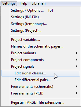
Image: The main menu "Settings"
In order to place differential pairs for Differential signaling it is clever to establish a signal class first. It is to determine minimum track width and minimum spacing between different signals. Later we will use this class for our differential pairs.
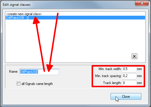
Image: The dialog "Edit signal classes"
In our example we create the new signal class DiffPairsUSB with minimum values of 0,5mm und 0,2mm for track width and track spacing. After having imported two components to the schematic we change over to the mode Place wire. Now we press keyboard key [o] for Options. In the opening dialog we select our new net class (=signal class), so that the tracks in the layout later will achieve the properties which we have determined here.
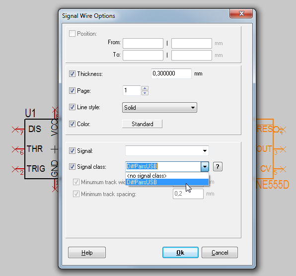
Image: The dialog Signal Wire Options
In the dialog "Signal Wire Options" we select the signal class we desire for our differential pairs.
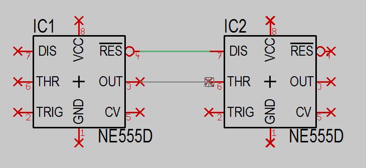
Image: Now we connect the pins using the "Place wire [2]" mode ![]()
File:Diffpairs5.png
Image: Change to the layout view.
After having imported the packages to the layout we choose menu option: "Settings/Edit Differential Pairs". From the right we select the pair of signals we like to treat. Using the arrow in the center of the dialog we shift them to the left in order to activate them for differential signaling.
File:Diffpairs6.png
Image: The signals OUT and |RES are going to be differential pairs.
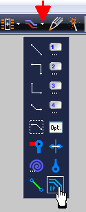
Image: Now use the extension of the icon "Draw track [2]" and select the button to "Draw a differential pair"
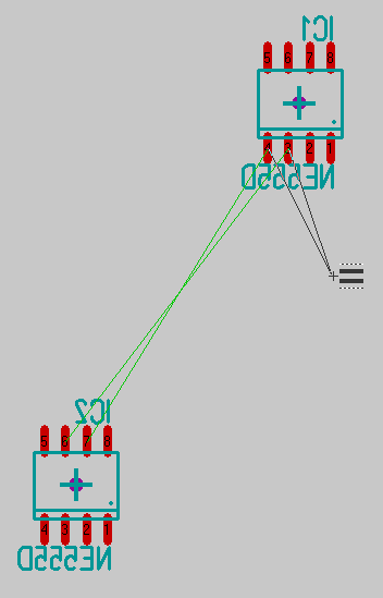
Image: Mauszeiger im "Differential Pair" - Modus.
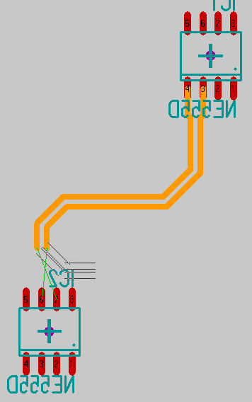
Image: Jetzt verlegt man die beiden Signale als parallel verlaufendes Doppelpack Segment für Segment. Leiterbahnbreite und -mindestabstand sind in der Signalklasse bestimmt, siehe oben.
File:Diffpairs10.png
Image: Kurz vor dem Anschluss an die Ziel-Pads, bricht man den Vorgang ab und weist TARGET an, die Bahnen NICHT fertig anzuschließen.
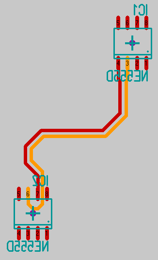
Image: So könnte der parallel verlaufende Leiterzug zweier unterschiedlicher Signale letzlich aussehen.

