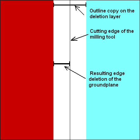
Spacing between GND copper and edge of the board
For this task, there are alternative proceedings, depending on your version:
From version 14.4.0.24:
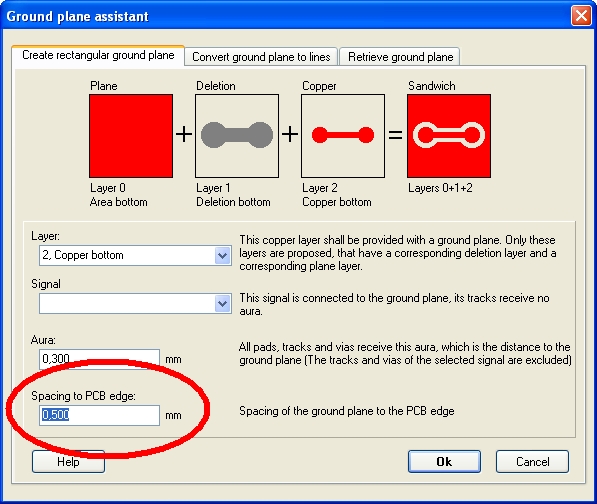
- When using the ground plane assistant: use option "Spacing to PCB edge" in tab "Create rectangular ground plane":
- When creating freehand ground planes: use menu "Actions/Ground planes/Spacing to PCB edge...
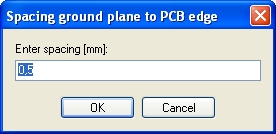
TARGET 3001! copies the contour of your board outline in given width upon all deletion layers. So the distance between the groundplane and the board edge is created. This is the dialog you will see:
Please note: The exact cutting edge is mid of line of the board outline (press the hash-key [#] to check that).
From version 13:
Copy the shape of your board outline to the copper layer on which your groundplane appears. Give the outline an "Aura". From version 13.5.0.115 bare lines can achieve an Aura. Eventually do a free Update .
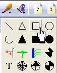
- With versions prior to V13: Draw a line with the drawing tool representing the spacing between Groundplane and the PCB edge upon the deletion layer (like a little frame). If you have a rectangular shape of the board outline, you may use the "Draw open rectangle" -tool.
By default the deletion layers are layer 1 (deletion copper bottom) and layer 15 (deletion copper top).
In case you have a more complex structure of the outline, you may copy the complete outline congruently on a deletion layer.
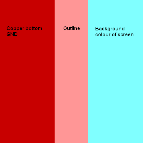
Considering the cutting edge always is middle of the line, half of the line width then would represent a spacing between the GND copper and the board edge.
Sure you can edit the width of the outline copy...
.


