You can reach this mode...

- Menu File / Print
- [Ctrl]+[p]
General
the printer preview shows exactly the page resp. the layers the way you have displayed them on screen. The same it is going to print. TARGET works WYSIWYG, what you see is what you get. If you want to print a different schematic page or a different layer set, you need to display it on screen. Since V16 you can select the different layers which will make your printed image directly within the print dialog (button "Visible Layers").
The printed area is defined by the space which the displayed elements need. So it might be good to have the outline layer visible. This makes sure to have captured all.
The options in the print dialog
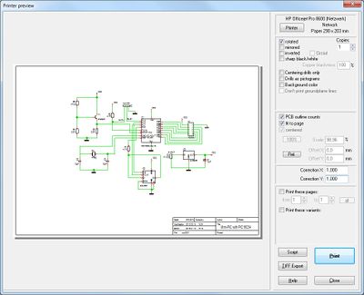
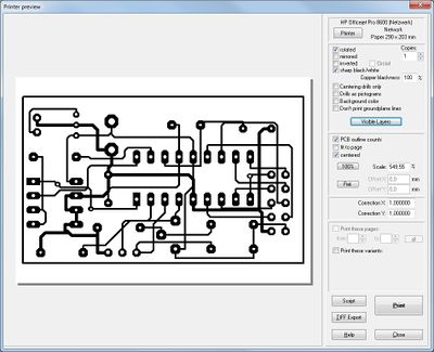
The schematic print preview of your current project (left). The layout print preview in "sharp black/white".
Select: Choose the desired printer within your hardware setup.
rotated, mirrored, inverted are self-explanatory
sharp black/white avoids shades of grey. This is important for photo reproduction of your layout. Blackness can be defined in percent.
Centering drills only: Drill holes will be printed in small for centered placement of your manual drill.
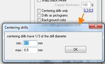
Image: Define drill widths of centering drills. min means: "at least" in the sense of: not lower than, max means: "highest though"
Background: Would one third of the drill diameter be very small, the main drill tool maybe would not find the hole because its tip is not really a tip but it is minimally flat. Would the diameter of the centering drill be too wide, the main drill tool would not find the center but would be edging around in the hole.
Drills as pictograms: Create a drilling plan for manual drilling. Drill holes of different sizes will be displayed using certain symbols (pictograms). A certain pictogram represents a certain drill diameter. In order to create a drilling plan it is necessary to activate option Drilling plan with pictograms in menu "File/Input-Output formats/Production". If you are wondering why your drill holes don't show up "open", please have a look whether Drills as pictograms might be ticked here. The same if you don't have Layer 24, Drill holes faded in.
Colors can all be made black by using the option "sharp black/white". In consequence there will be no copper areas printed in shades of gray.
No print of ground plane lines: Ground planes in TARGET can be converted in lines which then will be shifted to a copper layer. Due to clarity or for means of documentation it might be helpful not to have these ground lines printed.
In this case tick this box. Ground planes not converted to lines can separately be faded in or out by the area-layer they are on. As soon as a ground plane is converted to lines it shifts to the copper-layer. A fading out here effects that all other copper elements on it are faded out as well. This function avoids it.
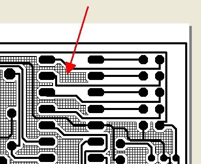
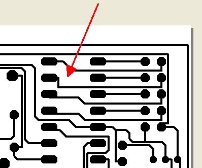
Images : Ground lines shown and hidden
The Scale of the print can be fixed in percent. Corrections in x- or y- direction can be done if the output would be distorted somehow. Using the Offset parameters it is possible to move the complete drawing within the sheet. fit to page enlarges the complete drawing to maximum size. Centered brings the whole view to the center in current scale.
Offset X, Offset Y: If you untick the boxes "fit to page" and "centered", you may enter the scale of your drawing individually. Using "Offset X" and "Offset Y" you can manipulate the positioning of your drawing on your sheet. If you tick: PCB outline counts every displacement refers to the pcb outline even if it is not visible in the picture.
Correction X, Correction Y: If your printer does not compute the image the way you expect, maybe the printed measurements vary from the ones on screen. Using Correction X, Correction Y allows to enter a factor for correction. Say your printed figure would have the measurement of 125 while it has 124 in the TARGET-view, you need to correct the axis in question by factor 124/125=0,992.
Buttons 100% and Rel.
![]()
Image: Print your PCB in 100% size (= real size)
![]()
Image: If your layout should have a relative origin, it will be positioned bottom left of the print. If there is no relative origin, the absolute origin will be shifted there.
TIFF-Export: Schematic or layout can be generated and compressed in format *.TIFF (see button "TIFF-Export").
Script: Say you would have to create a certain number of drawings of each of your projects with a certain identical layer configuration it can be exhausting and prone to errors to set the printer dialog every time new. Control your printing in this situation by a written advice (Script). How such a script can look like and how the syntax is, please see here: Printing script format.
A special case: How to print my DinA 3 schematic on two DinA 4 pages?
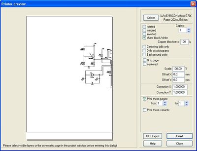
In order to print a DinA 3 schematic on two DinA 4 pages use the offset of the X-coordinates. Print the left part of the DinA 3 sheet as normal:
Now open the print dialog again and enter at "Offset X" value -210 mm. This is half the width of a DinA 3 page in mm. In our example we use -185 mm, half of a Din A3 drawing frame. The painting now shifts left on the abscisse (X-axis). Now print the right half of of the schematic. In the middle you may have an overlapping area. You may play a bit with the offset value.
Bring a big schematic into a drawing frame / Print a project as PDF
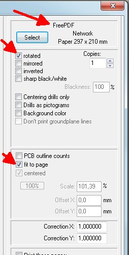
Sometimes one has created a big schematic and now has to bring it into a drawing frame afterwards. You could rip up your drawing and divide it using reference symbols. Time consuming and error prone. You could insert a DinA 2 drawing frame to the schematic and drag its left and upper corner as big that the complete schematic fits in. Now print the complete page as PDF. For doing so you might install the free PDF software FreePDF. If you press "Select" in the printer dialog you now can select "PDF" as well as the size of the page. Now you receive a PDF with a frame to which you can zoom in as deep as you like.
TARGET 3001!- files in documentations
You can Copy&Paste your schematic or layouts into your word processing program: Clipboard#Copying_to_MS-Word.2C_OpenOffice.2C_CorelDraw_...
Controlling the printer from TARGET 3001! by a script
It is possible to control the printer activities in TARGET 3001! by a script. See the particularities here:
Printing script format
Print invertedly (negative print negative)
...only works if you have a mosaic printer. Alternatively you can proceed using freeware software programs. Please check out how to do that: invertiert_drucken.pdf
Print grid points
Grid points can not be printed.


