Symbole de référence : Différence entre versions
| Ligne 1 : | Ligne 1 : | ||
| − | + | Un symbole de référence dans TARGET 3001 ! est utilisé dans le schéma. Il ressemble par exemple à l'un d'entre eux :<br><br> | |
| − | + | [[Image:e_reference.jpg|none]]<br><br> | |
| − | ou | + | |
| + | Cliquez sur [[Image:Ref.jpg]] sous [[Image:InsertComponent.jpg]]<br><br><br>. | ||
| + | ou appuyez sur la touche [R] du clavier ou utilisez l'option "Placer un symbole de référence" dans le menu "Composants".<br><br> | ||
[[Image:f_ReferencePins1_.jpg|none]]<br><br> | [[Image:f_ReferencePins1_.jpg|none]]<br><br> | ||
| − | |||
| − | [[Image: | + | Les îlots non connectés visuellement d'un même signal ou les connexions sur plusieurs pages du schéma doivent montrer leur correspondance/équivalent à l'aide de symboles de référence. Souvent, les connexions d'alimentation électrique sont dessinées par des flèches et des symboles de mise à la terre. Pour démarrer une telle connexion, utilisez cette commande de menu, cliquez sur le bouton ci-dessus ou appuyez simplement sur la touche ''''[R]''' dans la vue schématique. La boîte de dialogue s'ouvre pour sélectionner le symbole de référence préféré. Plus tard, après la connexion, le nom de broche visible doit correspondre au nom du signal. |
| + | |||
| + | |||
| + | [[Image:e_ReferencePins2.jpg|none]]<br><br> | ||
| + | |||
| + | Si ce n'est pas le cas, modifiez le symbole de référence après son placement avec [[Mousekeys|''M11''']] (Modifier le nom de la broche). Vous pouvez utiliser des symboles de référence pour créer des connexions sur plusieurs pages du schéma. Voir aussi [[Modifier composant]]. | ||
| + | |||
| + | See Reference symbols in use in this example: <br><br> | ||
| + | |||
| + | [[Image:RefsInUse.jpg|none]]Reference symbols used in a schematic with several pages. Refs can have various looks and various meanings. At the end they all carry a signal.<br><br><br> | ||
| + | |||
| + | == Design your own kind of reference symbol == | ||
| + | |||
| + | Signals in the schematic which need to be carried over several schematic pages or ilands of the same signal not being linked optically can be assigned to each other by the use of Reference symbols. | ||
| + | |||
| + | When creating a Reference symbol the following aspects need to be regarded: | ||
| + | |||
| + | Open a new project showing an empty schematic page. Automatically it will be named: NewProject.jpg. | ||
| + | Draw the reference symbol using the drawing functions of TARGET 3001! (line, connection pin, etc.).<br><br> | ||
| + | |||
| + | [[image:Ref1.jpg|none]]<br><br> | ||
| + | Click '''[[M11]]''' upon the pin name, the dialog "Change Texts" will open. | ||
| + | Enter the desired pin name in the "Content" field, e. g. SIGN-OUT.<br><br> | ||
| + | |||
| + | [[image:RefChgText1.jpg|none]]<br><br> | ||
| + | |||
| + | |||
| + | Highlight the reference symbol (drawings, connection pin) completely by dragging a highlighting square over all using '''[[M1H]]'''. | ||
| + | Place the cursor at the spot where later the handle cross shall appear, e. g. to the connection pin. | ||
| + | Press keyboard key '''[y]''' and immediately face the new handle cross.<br><br> | ||
| + | |||
| + | [[image:Ref2_e.jpg|none]]Image: Pin number "1" in gate "a" of a symbol (symbols can have more than one gate. Reference symbols are no gates but just a connector). These little prefixes have no crucial meaning for a reference symbol.<br><br> | ||
| + | Now click '''[SHIFT]''' + '''[[M11]]''' (or just '''[[M11]]''') upon the connection pin. The dialog "Change pins" appears:<br><br> | ||
| + | |||
| + | [[image:Ref3_e.jpg|none]]<br><br> | ||
| − | + | Untick the box "Show pin number". | |
| + | Tick the box "Is reference-pin". Dont tick this box prior to the use of the '''[y]''' key. Otherwise you will receive the error message: "Pin already connected to a signal!". | ||
| + | Give a signal name to the pin by the use of the button '''"Edit pin name"'''. If you prefix an exclamation mark you will make this signal name a variable and thus before any import you'll get asked which signal name you'd like to use. If you abandon the exclamation mark ther won't be a questioning prior to import. The signal name you had entered to the field in question will be directly used in the schematic. | ||
| − | + | Press '''OK''' ([Enter]-key). | |
| + | Highlight the complete reference symbol again by a highlighting square. | ||
| + | Press keyboard key '''[x]'''. The dialog "Export symbol" appears.<br><br> | ||
| − | + | [[Image:SymbExportierenRef_e.jpg|Dialog:Export symbol|none]]The dialog ''Export symbol''<br><br> | |
| − | |||
| − | |||
| − | + | *From the list on the left select the component type "Reference symbols" from the "Voltage and current" group. Search e.g. by ''reference'' and tick the box "Only hits". | |
| + | *In the "Insert component name" area, enter a component name in the "English" language field, for example ''My SIGN-OUT'' - just to divide it from others by the name. | ||
| + | *For "Manufacturer", select "not clear". | ||
| + | *Further properties can be optionally assigned in the middle area of the dialog. | ||
| + | *A package is not required, so leave this field blank. | ||
| + | *The entry "Ref" should appear automatically for Component prefix. | ||
| + | *Now press the "Save component" button. | ||
| + | *A package proposal is not required, so negate the question about a package for the PCB in the dialog popping up. | ||
| + | *The additional safety question whether the component should be a reference symbol please confirm by "Yes". | ||
| + | *The next dialog to edit the symbol just closed with the red X in the upper right corner. | ||
| + | <br><br> | ||
| − | + | If you press the [r] key in the schematic view, you are taken directly to the reference symbol selection. The reference symbol you have just drawn appears in the list with its name and USER flag and can instantly be imported into the schematic.<br><br><br> | |
| − | |||
| − | |||
| − | |||
| − | |||
| − | |||
| − | |||
| − | |||
| − | |||
| − | |||
| − | |||
| − | |||
| − | |||
| − | |||
| − | |||
| + | [[de:Referenzsymbol]] | ||
| + | [[category:Components/Libraries]] | ||
| + | [[fr:Symbole de référence]] | ||
| − | |||
| − | |||
| − | |||
Version du 28 janvier 2019 à 14:56
Un symbole de référence dans TARGET 3001 ! est utilisé dans le schéma. Il ressemble par exemple à l'un d'entre eux :
Cliquez sur ![]() sous
sous ![]()
.
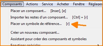
ou appuyez sur la touche [R] du clavier ou utilisez l'option "Placer un symbole de référence" dans le menu "Composants".
Les îlots non connectés visuellement d'un même signal ou les connexions sur plusieurs pages du schéma doivent montrer leur correspondance/équivalent à l'aide de symboles de référence. Souvent, les connexions d'alimentation électrique sont dessinées par des flèches et des symboles de mise à la terre. Pour démarrer une telle connexion, utilisez cette commande de menu, cliquez sur le bouton ci-dessus ou appuyez simplement sur la touche '[R] dans la vue schématique. La boîte de dialogue s'ouvre pour sélectionner le symbole de référence préféré. Plus tard, après la connexion, le nom de broche visible doit correspondre au nom du signal.
Si ce n'est pas le cas, modifiez le symbole de référence après son placement avec M11' (Modifier le nom de la broche). Vous pouvez utiliser des symboles de référence pour créer des connexions sur plusieurs pages du schéma. Voir aussi Modifier composant.
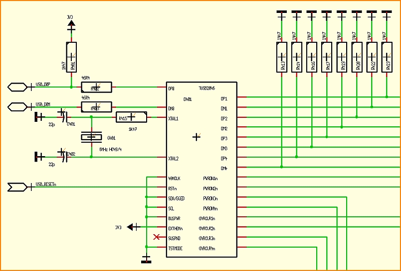
See Reference symbols in use in this example:
Design your own kind of reference symbol
Signals in the schematic which need to be carried over several schematic pages or ilands of the same signal not being linked optically can be assigned to each other by the use of Reference symbols.
When creating a Reference symbol the following aspects need to be regarded:
Open a new project showing an empty schematic page. Automatically it will be named: NewProject.jpg.
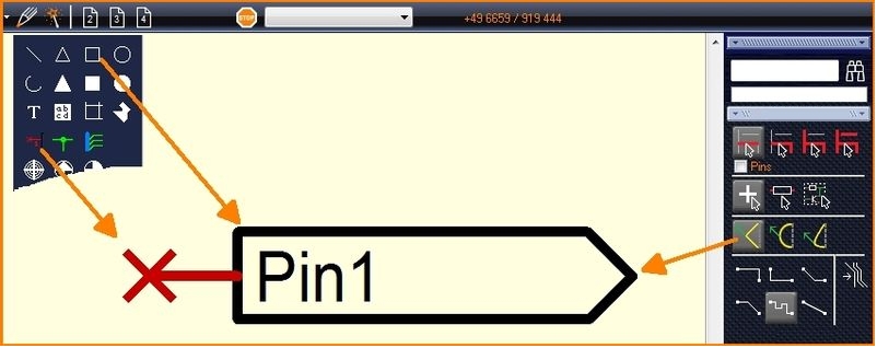
Draw the reference symbol using the drawing functions of TARGET 3001! (line, connection pin, etc.).
Click M11 upon the pin name, the dialog "Change Texts" will open.
Enter the desired pin name in the "Content" field, e. g. SIGN-OUT.
Highlight the reference symbol (drawings, connection pin) completely by dragging a highlighting square over all using M1H.
Place the cursor at the spot where later the handle cross shall appear, e. g. to the connection pin.
Press keyboard key [y] and immediately face the new handle cross.
Now click [SHIFT] + M11 (or just M11) upon the connection pin. The dialog "Change pins" appears:
Untick the box "Show pin number". Tick the box "Is reference-pin". Dont tick this box prior to the use of the [y] key. Otherwise you will receive the error message: "Pin already connected to a signal!".
Give a signal name to the pin by the use of the button "Edit pin name". If you prefix an exclamation mark you will make this signal name a variable and thus before any import you'll get asked which signal name you'd like to use. If you abandon the exclamation mark ther won't be a questioning prior to import. The signal name you had entered to the field in question will be directly used in the schematic.
Press OK ([Enter]-key).
Highlight the complete reference symbol again by a highlighting square.
Press keyboard key [x]. The dialog "Export symbol" appears.
- From the list on the left select the component type "Reference symbols" from the "Voltage and current" group. Search e.g. by reference and tick the box "Only hits".
- In the "Insert component name" area, enter a component name in the "English" language field, for example My SIGN-OUT - just to divide it from others by the name.
- For "Manufacturer", select "not clear".
- Further properties can be optionally assigned in the middle area of the dialog.
- A package is not required, so leave this field blank.
- The entry "Ref" should appear automatically for Component prefix.
- Now press the "Save component" button.
- A package proposal is not required, so negate the question about a package for the PCB in the dialog popping up.
- The additional safety question whether the component should be a reference symbol please confirm by "Yes".
- The next dialog to edit the symbol just closed with the red X in the upper right corner.
If you press the [r] key in the schematic view, you are taken directly to the reference symbol selection. The reference symbol you have just drawn appears in the list with its name and USER flag and can instantly be imported into the schematic.
fr:Symbole de référence
.


