Le dialogue de la sortie STEP 3D
Sommaire
Abstract
STEP = STandard for the Exchange of Product model data
Find the dialog for the STEP Export in menu:
File|Input/Output Formats|File transfer/documentation|Step export(3D)...
Fichier:Step dialog1 e.jpg
Image 1: The Step Export Dialog as it opens. It consists of the main sections Schnellauswahl und Details.
The section Quick selection
Fichier:Step Schnellauswahl e.jpg
In externem CAD die komplette Platine für das Gehäuse überprüfen
Diese Option verwenden Sie, wenn Sie den kompletten Aufbau (Platine incl. Bestückung) exportieren möchten. Es fehlen nur die inneren Details im Platinenkörper, die man von außen nicht sieht. Die Massefläche fehlt hier, kann aber noch hinzu gewählt werden.
In externem CAD nur die reine Platine für das Gehäuse überprüfen
Diese Option verwenden Sie, wenn Sie nur den Platinenkörper, also das, was gemeinhin in FR4-Material gefertigt wird, exportieren möchten.
Platine mit externen Werkzeugen elektrisch überprüfen
Hier übergeben Sie den Platinenkörper mit allen inneren und äußeren technischen Details (Leiterbahnen, Pads, Vias, Bohrlöcher...) ohne Bauteile.
Der Dialogbereich Details
Die folgenden Reiter können gewählt werden:
AP = Application Protocol
STEP = STandard for the Exchange of Product model data
AP = Application Protocols
En STEP il y a des protocoles d'application pour les sections différentes:
- AP 203 Configuration Controlled Design
- AP 210 Electronic Printed Circuit Assembly, Design and Manufacturing
- AP 214 Core Data for Automotive Mechanical Design Processes
Votre sortie 3D soutient en général seulement quelques protocoles d'application! Votre système doit avoir le protocole élémentaire 203. Dans les données de sortie vous voyez seulement une différence:
- STEP AP 203: monochrome
- STEP AP 210: quadrichrome
- STEP AP 214: quadrichrome
Selection
In tab Selection determines which elements are going to be overgiven to the STEP format. No changes have taken place here since the last version.
Detail truth
Components in color or monochrome.
Créer le contour du PCB avec des coordonnées exactes:
Le calcul de la surface d'un objet 3D est un algorithme qui a une imprécision de quelques µm. Pour le contour du PCB, un algorithme différent peut être sélectionné qui évite cette imprécision.
The outline of the PCB is calculated by an algorithm which shows an impreciseness of a few µm. You can select a precise algorithm which avoids this.
Output ground plane:
A ground plane can be converted to STEP though in the TARGET 3D viewer upt to now (may 2014) it can not be displayed. Activate this box if indicated.
Output details for simulators (conducting via hull and solder with THT):
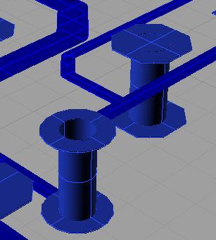
Abundance of details goes along between the poles of necessity and file size. To simulate the electrical behaviour of the 3D PCB sufficiently details are needed. Tick the box here so that the STEP exportembraces it accordingly. Ground planes and assemblies are ticked automatically. The quick selection also ticks the required boxes automatically. "Components" are unticked because they aren't needed for simulation.
The layout of the printed circuit board, the placement of the components and the structure of the power layer can have its own effect on the electrical performance of the circuit. There may be problems with EMC, power integrity and signal integrity. Below you will find helpful links on the subject. By this means you can analyse your board on such effects for example using the simulation tool CST.
https://www.cst.com/Products/CSTPCBS
https://www.cst.com/Applications/Category/Signal+Integrity+and+Power+Integrity
https://www.cst.com/Applications/Article/Signal-Integrity-Analysis-Of-A-Complex-Multi-Layered-Package
http://en.wikipedia.org/wiki/Signal_integrity
http://en.wikipedia.org/wiki/Computational_electromagnetics
Sizes (= parameters)
Extras
Using the option "Generate assemblies the STEP-Import in your CAD might show a hint e.g. in Rhinoceros
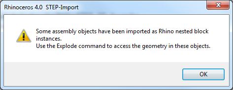
In your CAD there will be a function "Explode", which is able to divide objects in a hierarchy (cascading).
Fichier:Step dialog72.jpg
PIC exploded:
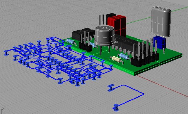
Importantelement groups san be divided into various sub entities. A first explosion separates the following objexts:
- PCB body
- electroconductive objects (Tracks, Pads, Vias, Ground planes...)
- component 1
- component 2
- component ...
In this first stage of explosion within your 3D CAD system it is possible to assign material properties (e.g. "copper") to the electroconductive objects of your projects. Now let the electroconductive parts explode again so that single signals for instance can be touched/inspected/treated separately (galvanic separation).
Approximations
Quelques logiciels 3D ont seulement un importation rudimentaire de STEP. Par exemple CYLINDRICAL_SURFACE ne sont pas implementé dans les surfaces de STEP. Ici, la surface peut être approché par un polyèdre, çà veut dire on peut utilisé seulement des PLANEs.
Temps de charger un fichier
Le temps de charge peut prendre quelques minutes! Le temps de charge est prolongée si le polyèdre est utilisé pour le rapprochement. Le voyeur 3D peut exécuter plus rapidement l'importation que les logiciel de CAO 3D! Eléments de STEP actuellement utilisé: CARTESIAN_POINT, VERTEX_POINT, LINE, CIRCLE, PLANE, CYLINDRICAL_SURFACE, TOROIDAL_SURFACE, SPHERICAL_SURFACE, DIRECTION, VECTOR, AXIS2_PLACEMENT_3D, ADVANCED_FACE, FACE_BOUND, FACE_OUTER_BOUND, ORIENTED_EDGE, EDGE_CURVE, EDGE_LOOP, CLOSED_SHELL, MANIFOLD_SOLID_BREP, STYLED_ITEM, MECHANICAL_DESIGN_GEOMETRIC_PRESENTATION_REPRESENTATION
Désactivez toutes les options pour le chargement en Solid Edge pour raccourcir:
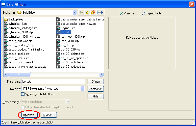
Excusez! Nous n'avons pas un inmage du dialogue de SolidEdge en Francais.
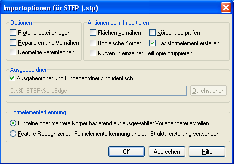
Excusez! Nous n'avons pas un inmage du dialogue de SolidEdge en Francais.

