« MID Tutorial » : différence entre les versions
| Ligne 24 : | Ligne 24 : | ||
Pour supprimer un boîtier du corps 3D encore, simplement cliquez sur le centre du boîtier (pour marquage) et poussez le touche clavier '''[Sup]'''.<br><br><br><br><br><br> | Pour supprimer un boîtier du corps 3D encore, simplement cliquez sur le centre du boîtier (pour marquage) et poussez le touche clavier '''[Sup]'''.<br><br><br><br><br><br> | ||
= | = Tourner un composant par degré = | ||
Immediatement il est placé et un autre dialogue permet tourner par degré.<br><br>[[Image: mid_tutorial_f_6.jpg]]<br>Image: Boîtier placé, tournez eventuellement.<br><br> | |||
<br><br>[[Image: mid_tutorial_f_6.jpg]]<br>Image: | |||
Positive turn means counter clockwise, negative means clockwise. You also might enter degrees here individually. OK closes this dialog. Now that we are still in the mode to place parts, we just hover to the next position. The same here. Fist click the desired spot, then select a part from the list. We select IC number two and place it. Again we can rotate the part. You can make this dialog pop up at any later time. Please highlightthe part and press keyboard key '''[t]''' for "ro<u>t</u>ate".<br><br> | Positive turn means counter clockwise, negative means clockwise. You also might enter degrees here individually. OK closes this dialog. Now that we are still in the mode to place parts, we just hover to the next position. The same here. Fist click the desired spot, then select a part from the list. We select IC number two and place it. Again we can rotate the part. You can make this dialog pop up at any later time. Please highlightthe part and press keyboard key '''[t]''' for "ro<u>t</u>ate".<br><br> | ||
Version du 22 décembre 2016 à 15:04
Démarrer dessigner dans un corps 3D
Vous avez un schéma et désirez dessiner les composants dans un corps 3D (MID, Molded Interconnect Device). Le bouton "3D" à droit en haut dans vue schéma seulement ouvre un page blanc parce que d'abord nous devons importer un corps 3D. Dans menu "Actions" utilisez l'option "Prepare MID...". Un browser s'ouvre pour sélectionner un fichier en format STEP (*.stp). Il est le corps pour afficher les composants et dessiner les pistes. Plus tard ouvrez le vue 3D poussant le bouton 3D dans la barre d'outils dans vue schéma.
Dans le vue layout 2D en TARGET, au origine de rèpere 0|0, maintenant un poignée est visible. Il réprésent l'objet 3D. Si vous voudrais supprimer le corps importé, vous devez supprimer ce poignée dans le vue layout 2D. Pour information: Un double click sur le poignée montre que les proprietés du boîtier ont l'inscription IS_MID_COMPONENT avec le valeur TRUE.
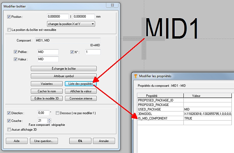
Image: Dans le layout 2D un boîtier spéciale sera "preparé". Il east fait automatiquement. Nul besoin de faire quelque chose.
Nos avons une construction à la façon d'un plastic bouchon. Il est l'ossature pour appliquer des èlements accordant du schéma.
A gauche dans le dialogue nous voyons tous les signaux et aussi tous les boîtiers qui sont déterminé par schéma. Les propositions de boitier sont considérées dans la coulisse.
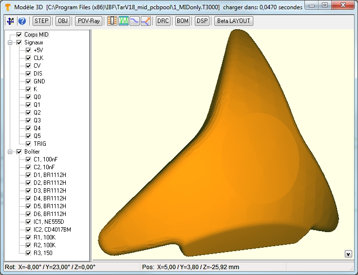
Image: Le vue 3D montre un corps sur lequelle des composants (boîtiers) et des pistes seront appliqué.
Placer un composant sur la surface du corps 3D
Utilisez button ![]() pour placer un composant (son boîtier) sur le corps. l'image du curseur change
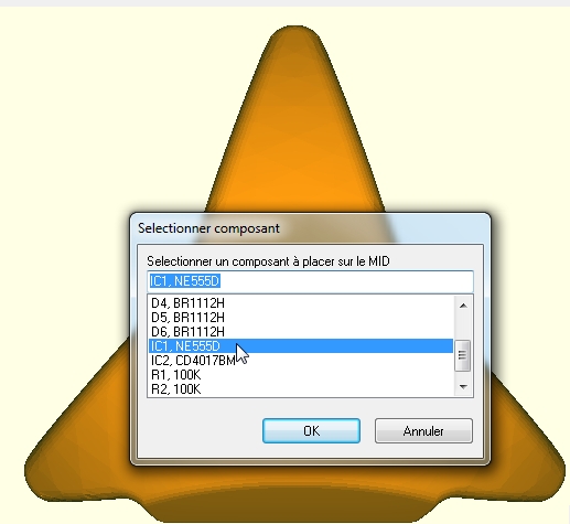
pour placer un composant (son boîtier) sur le corps. l'image du curseur change  et vous pouvez il déplacer vers le location désiré sur le corps. L'espace de orintation est le centre du boîtier. Un click sur la position fait un dialogue apparaître qui permet de roter le boîtier graduellement.
Dans le cas présent nous choisissons IC numero un, le composant timer NE555D.
Pour supprimer un boîtier du corps 3D encore, simplement cliquez sur le centre du boîtier (pour marquage) et poussez le touche clavier [Sup].
Tourner un composant par degré
Immediatement il est placé et un autre dialogue permet tourner par degré.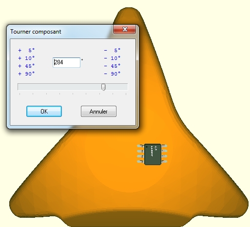
Image: Boîtier placé, tournez eventuellement.
Positive turn means counter clockwise, negative means clockwise. You also might enter degrees here individually. OK closes this dialog. Now that we are still in the mode to place parts, we just hover to the next position. The same here. Fist click the desired spot, then select a part from the list. We select IC number two and place it. Again we can rotate the part. You can make this dialog pop up at any later time. Please highlightthe part and press keyboard key [t] for "rotate".
Move a component, adapt its position
If the position might need a better placement so we highlight the part by a click to its center, move the cursor to the desired spot and press keyboard key [d] to "displace". Immediately the package moves its center to the new spot, defined by the cursor tip. If the new place should not have the same inclination in space, you again might need to rotate it a bit. Repeat this action if needed.
Component is elevated a bit
If you rotate the body you will see that the tips of the leads are elevated a bit. These zero point two millimeters are OK and covered by the constructional process. It can be set in the Design Rule Check (DRC) dialog.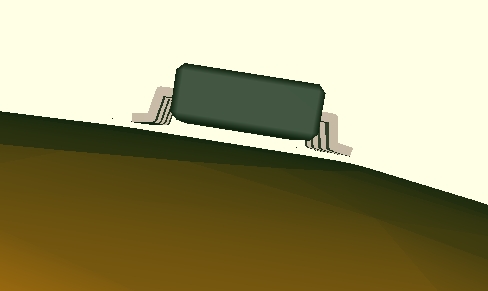
Image: Component elevated
Calculate the air wires
Use button: ![]() For these two parts we'd like to see the connections coming from the schematic. Creating the air wires gives information which connections now need to be routed. For a better view we fade out the packages for a moment. Untick the box (arrow). It is recommended to recalculate the air wires from time to time.
For these two parts we'd like to see the connections coming from the schematic. Creating the air wires gives information which connections now need to be routed. For a better view we fade out the packages for a moment. Untick the box (arrow). It is recommended to recalculate the air wires from time to time.
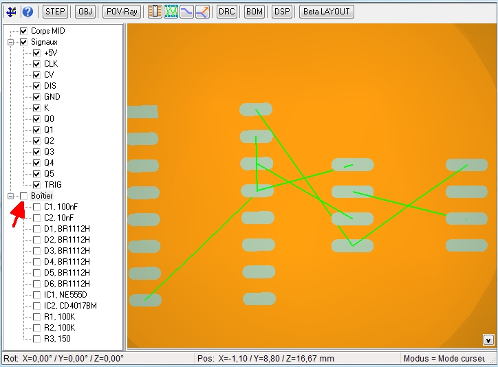
Image: Air wires calculated, the bodies of the two faded out
We look at the diagonal connection to the right we now would like to rout.
Place tracks
We use the button to place a track ![]() while instantly the cursor changes
while instantly the cursor changes ![]() If we come close to a pad a little snap on-box appears helping to meet the connection right.
If we come close to a pad a little snap on-box appears helping to meet the connection right.
Such a snap on box only appears at pads which have a signal being defined in the schematic. Pads with no signal don't show a snap on box.
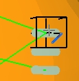
Image: Snap on boxes in mode "Place tracks"
A click on the pad starts the track. The width of the track in black and its spacing in red are determined by the signal characteristics in the schematic.
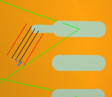
Image: Snap on boxes in mode "Place tracks"
Each click places a piece of track. If you didn't manage to place the track neatly you can correct the route later. It is good to click often in order to create many little segments, easy to adapt lager to a smooth route. At least we arrive at the destination pad.
With [ESCAPE] you release the cursor from any mode and return to pointer mode.
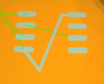
Image: Placed track, needs to be adapted a bit.
Drag the corner of a track
Now we'd like to adapt this corner by dragging it into shape. Use the drag corner mode ![]() do a simple click to the corner while the image of the track segment changes. Now just move the mouse without key action
do a simple click to the corner while the image of the track segment changes. Now just move the mouse without key action
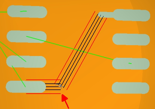
Bild: Enfachklick und lediglich die Maus bewegen.
If you have found the position just place it by a single click. You still can adapt the width of a track. Highlight it and press keyboard key [e] for edition.
We change the track width for example to zero point one millimeters. This will cause an error later when we start the design rule check.
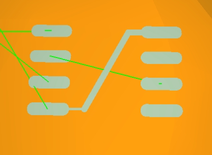
Image: Placed track. The air wire vanishes as soon as all airwires are calculated new (on button click.)
Also spacing violations: How to check them and how to correct them? So here we deliberately cause a spacing violation by placement of the track too close to a neighboured pad.
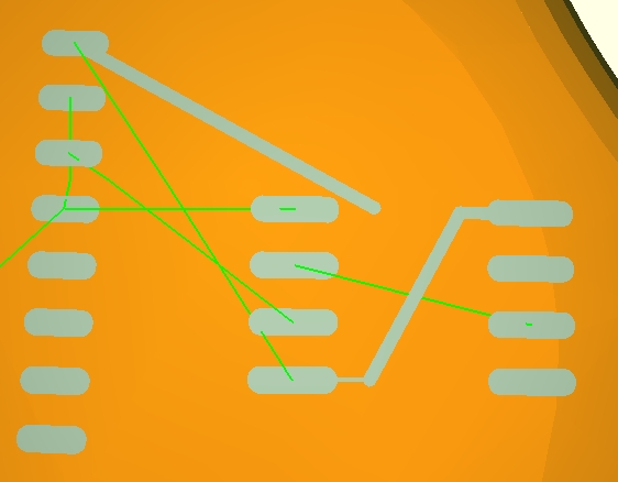
Image: The track above possibly will come too close to another, at the lower connection maybe the track is too thin...
Design Rule Check
Now we start DRC the design rule check. It checks whether all components are placed, whether all signals are routed, all pins touch the ground with a certain tolerance given.
Also the width of tracks as well as spacings and schort circuits can be checked. When it is started it shows some packages missing as well as airwires left which is clear to us. But at the bottom of the list we see the hints "Segment too thin" and "Spacing violation" and this is what we have caused.
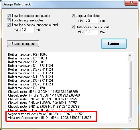
Image: The Design Rule Check in our example.
Every error is represented by a marker. Each one can be clicked to get information what it stands for. If clicked, the element in question is highlighted. Pressing keyboard key [e] allows to edit it. The same with the spacing violation. Just click the end and drag it into position or delete it and to draw it new.
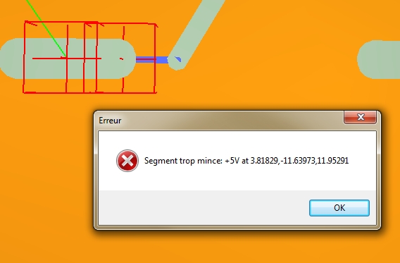
Image: Click on a marker explains the error. Clicking OK highlights the element in order to edit it by [e].
Error markers can be deleted by the DRC dialog.
If all parts and tracks are properly placed, you may come to something like that (below). Any part can be deleted at any time, any track can be adapted at any time. You always have the schematic in the background. So any change of the electronic logic in the schematic can instantly find its consistent representation on your 3D construct.
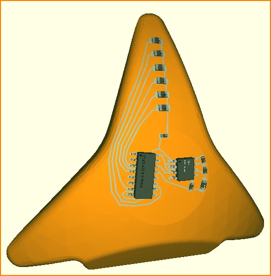
Image: Layout, ready for manufacture (body as well as assembly).
STEP Format
To produce it you just would export all to a STEP file to hand it over to the manufacturer of your choice. ![]() Sure you can produce it yourself. The STEP format is industry standard.
Sure you can produce it yourself. The STEP format is industry standard.
Bill Of Material
Regarding the assembly you first might want to have a lok at the Bill Of Material (BOM). It is a simple text file which can be read by any text editor giving any opportunity for formatting. All components in use are listed as well as their orientation angles including azimuth and zenit angles.
Image: The Bill of Material, BOM
Dispenser information
The same with dispenser information (Button DSP) in order to apply the solder agens to the pads. In addition to the name of the component all its pad coordinates are listed.
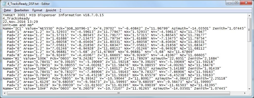
Image: Dispenser information as text file
Order the project as a completely manufactured and assembled part
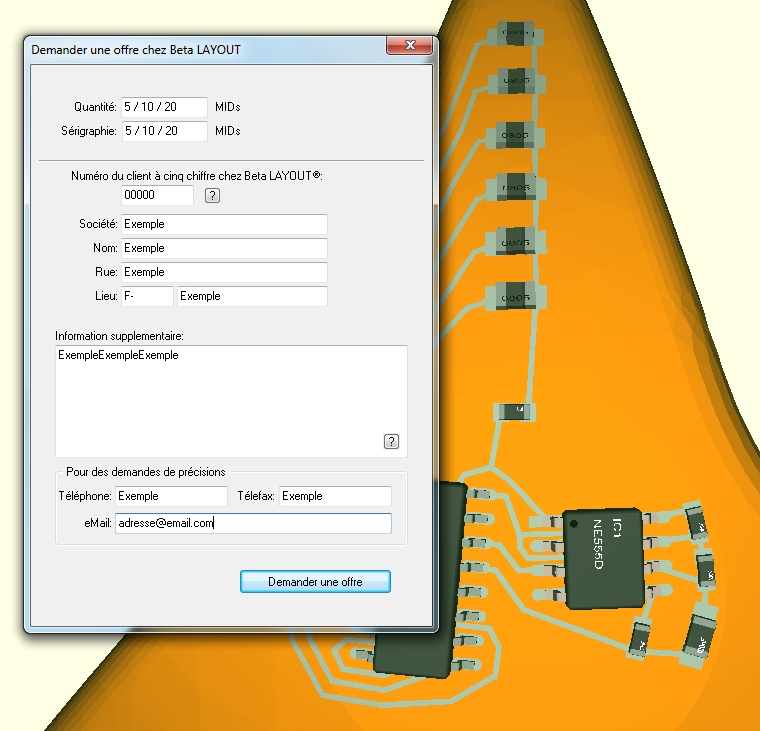
If you want to order the completely produced and assembled part as a whole, just click the Beta LAYOUT TAB to request an offer from there. You only need to define the quantity, enter your personal data maybe give some additional instructions and press the "Request offer" button. An eMail is sent to Beta LAYOUT having your file appended and you will have an answer soon.


