Page
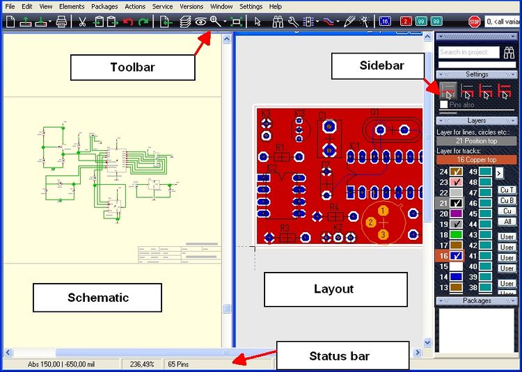
Organise and handle schematic pages within the Sidebar on the right edge of screen. In the sidebar please see section "Schematic Page".
Contents
- 1 General
- 2 Administration of schematic pages
- 3 Lead a signal to a second page
- 4 Spread a symbol over several schematic pages
- 5 Go to page
- 6 Next/Previous Page (schematic)
- 7 Bring an object to a new schematic page
- 8 Migrate a schematic page to another project
- 9 Reference symbols with pages of use
- 10 Special: How to print a Din A3 schematic page on two Din A4 pages
General
Image: The canvas of schematic and layout. More detailed see the Sidebar article.TARGET 3001! is able to handle up to 100 schematic pages within each project which you can browse. The maximum size of the sheets/boards is 1.2square meters or 47.24 square inches. Open a second page in the schematic view by pressing the icon:
Image: Open another page
Open a third page by pressing the 3 and so on. On which page you currently operate please see here:
Image: The currently open page - It's the one you are working on.
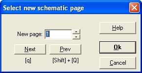
If you click M1H or M2on this left icon a dialog appears allowing the selection and naming of a different page. In case you are using more than one schematic page you can switch to the next one by the use of the [q] key or to the previous one by [Shift]+[Q].
Administration of schematic pages
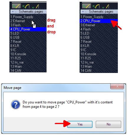
- From version 14 schematic pages can be administrated by the sidebar section "Schematic pages". You can touch the bar (M1H) and pull it up and down.
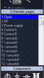 | 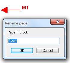 | 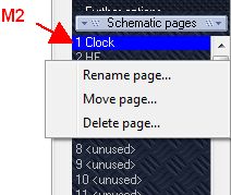 |
A line represents a schematic page, a click on it allows editing it's name. You also can touch a line and drag it to a different position in the row.
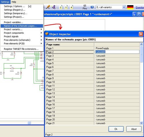
- In TARGET 3001! versions younger than V13.3.0.62 the schematic pages are handled in Dialog "Settings/Names of schematic pages".
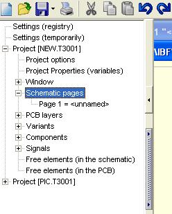
- In versions older than V13.3.0.62 the administration of schematic pages is managed in the Hierarchy Browser (see on the left edge of screen for. Use M2 and reach "Properties". After selecting it, the following dialog appears:
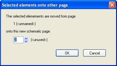
In case you intend to shift the contents of Page 4 to page 5 highlight the complete schematic page by M1H. Press [e] and enter the desired schematic page to the flashing dialog. This works in later versions as well:
Lead a signal to a second page
Use a Reference Symbol or a bus.
Spread a symbol over several schematic pages
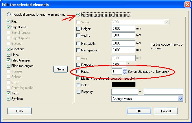
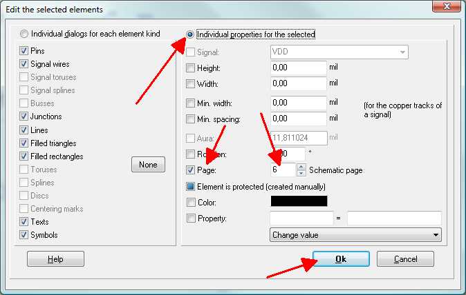
The easiest way to move symbols and wires from one schematic page to another is to select them, press [e] for edit and change their page number:
Please make sure that the coordinate space on the target page is free before letting the drawing fall into that page.
Have a close look at the components which consist of several symbols: Do they still have the same component number? If not, they are parts of different ICs. Then delete each symbol with the higher component number and reinsert the right one. E.g. IC3a and IC3b belong together with IC15c and IC15d. Delete IC15c and insert IC3c at the same position using the menu option "Import Rests of Components" in menu "Components".
Go to page
You can select another page to be viewed in a schematic window, by click on the icon representing the page currently active. Use [q] or [Shift]+[Q]
Next/Previous Page (schematic)
Use key [q] for changing to another schematic page, if you use more than one schematic pages.
Use keys [Shift]+[q] for changing to the previous page, if you use more than one schematic pages.
Bring an object to a new schematic page
In schematic menu "Edit" the entry "Bring to new page" offers the following ption:
The desired object needs to be highlighted first. At the edge of schematic page #1 there are reference symbols placed automatically. They can be displaced individually.
Migrate a schematic page to another project
A customer asks:
"Is there any way to move the complete contents of a schematic page of project A to a page of project B without changing component numbers? I have tried copy/paste, selecting "All signals keep their names", but the component numbers still move to empty spaces. If there is any other way to do this, it would be very good. However, I would have to do the same with the associated layout page."
Response:
"First, open both projects in the same TARGET. The menu item "Window" then helps with the organisation.
Please catch the corresponding page with a catch window completely and make a module out of it. With the current version of TARGET, the housings and the relevant tracks in the PCB are then automatically assigned to this module as well.
Then use the clipboard to copy the circuit diagram view of the module into the other project and immediately afterwards the circuit board part of the module.
Keeping the numbering of the components does not work, TARGET always takes the next free number. Using the "Reorganisation" in the menu "File" you may renumber the components of the new page afterwards.
Reference symbols with pages of use
A reference symbol can show on which other pages the signal appears. Please have a look here:
Reference symbols with pages
Special: How to print a Din A3 schematic page on two Din A4 pages
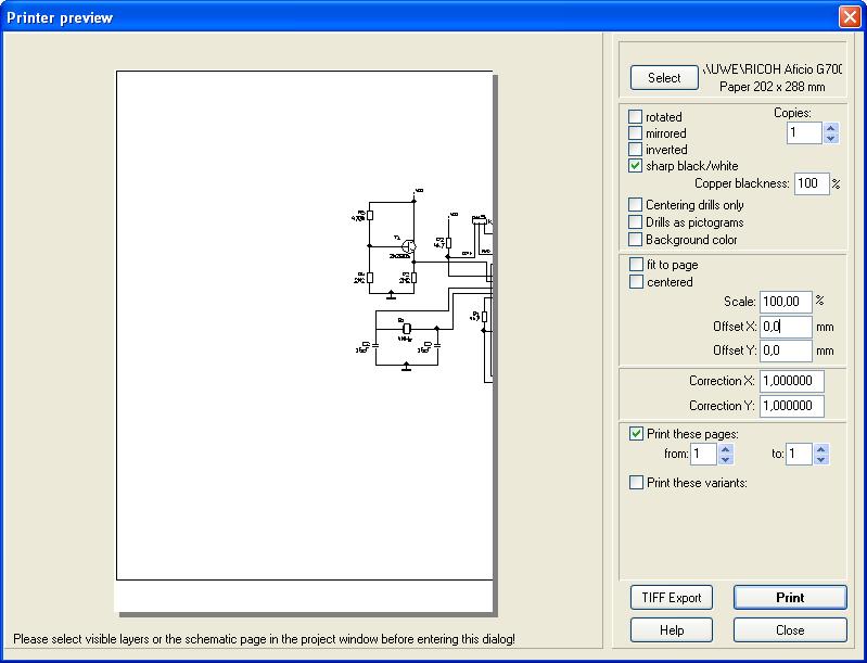
To print a Din A3 schematic page on two Din A4 pages please use an offset of the X-coordinates. Begin printing the left part of your drawing without offset using the following settings:
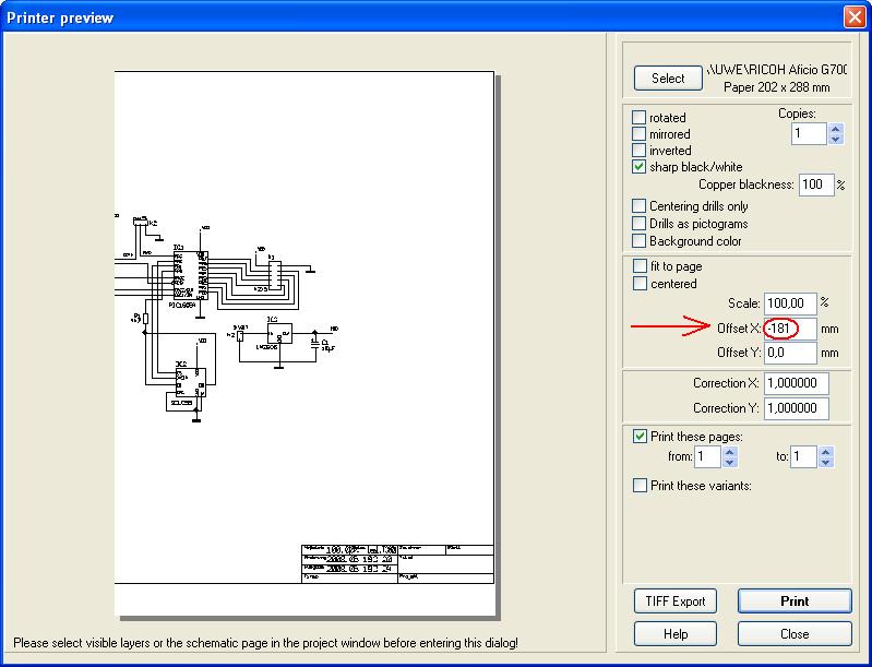
Open the Print dialog again and enter an "Offset X" at -210 mm (half the length of a Din A3 page = width of a Din A4 sheet). The drawing shifts left left according to the entered coordinates. In our example we choose a value of -181 mm for using the space as best as possible because the width of the drawing frame is a bit smaller.
Now print the right half of of the schematic. In the middle we will have a overlapping area. You may play a bit with the offset value.


