Difference between revisions of "Line"
(→Trim lines) |
(→Trim lines) |
||
| Line 85: | Line 85: | ||
[[Image:LinienTrimmen7.png]]<br>'''Image 7:''' Delete. | [[Image:LinienTrimmen7.png]]<br>'''Image 7:''' Delete. | ||
| + | |||
| + | |||
| + | |||
| + | |||
| + | [[Image:kontextmenu_e.jpg]]<br>'''Image 8:''' Context menu: Untick line if ticked | ||
| + | |||
| + | |||
| + | <br><br> | ||
== Shift lines == | == Shift lines == | ||
Latest revision as of 16:40, 28 July 2021
Contents
You can reach this mode
by [Ctrl]+[2] (do not use the "2" in the numbers block of the keyboard) or
by "Draw Line" in Menu Elements or
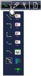
by the tool ![]() under the icon
under the icon ![]()
Pleae note:
Drawing a line does not mean placing a signal track! A line in TARGET is just a kind of painting and can not achieve electrical functions. Lines are used e.g. for the drawing of outlines of component symbols or packages (upon layer 21 Position top or layer 7 Position bottom), for the outline of the whole board (upon layer 23 Outline), for the imaging of a bridge e.g. on layer 21 position top, for the force lines between corresponding potentiometers, between inductivity and contact of a relay and for any kind of drawing upon any kind of layer. For drawing signals and tracks please use the icons: ![]() and
and ![]()
What you can do...
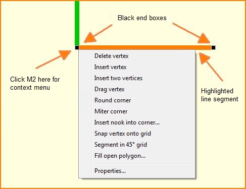
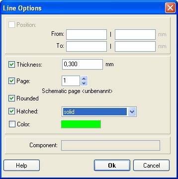
Press [o] (for options) for line settings. A M1 click creates the first segment. Use further M1 clicks to draw a polyline. Also use the drag-function [g]. Click M1 upon a line and grab one of the little black touchpads at the ends of the highlighted line by M1H and drag it to the desired spot. Add vertices by pressing M2 on a box and follow the context menu.
Image: Right mouse key M2 on a black touchpad of a line opens the context menu
Set the bending mode here:
Using the space bar toggles between "neighboured" bending modes during the placemnet of lines. See also Drag.
Leave this mode
by [ESC] or M12
Line Options
Rounded: The ends of the line segment have round caps. This causes smart connections of segments when sharp bending.
Hatched: Hatched lines can be used for the force lines between corresponding potentiometers and between inductivity and contact of a relay (line options).
Lines show too wide
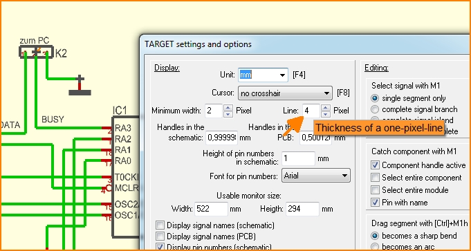
Please have also a look at menu "Settings / Settings-Options" and define how wide a one pixel line really shall display:
Image: Define the real line width of a one pixel line.
Trim lines
Lines crossing each other can be trimmed (=deleted) to the point of intersection. Please find this function in menu Actions/Trim lines. Highlighted lines will be converted to segments so that parts of the lines can be deleted.
A full circle, for example, must always be cut at two positions the same time. If a line starts inside the circle and ends outside the circle, only the line will be cut into two pieces after "Trim lines" was used. The circle itself closes again "from behind" thus is cut only at one position. Only if at least 2 lines intersect the circle the way described, or one line intersects the circle two two, two arcs of the circle will be created. So at least 2 intersections within a full circle are needed.
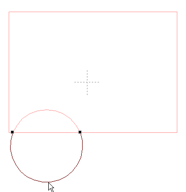
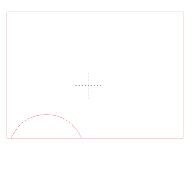
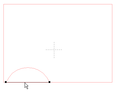
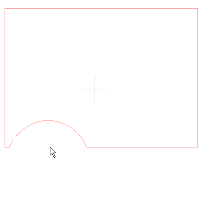
The following example shows how to create an inner outbreak within the PCB outline having the shape of a segment of a circle:
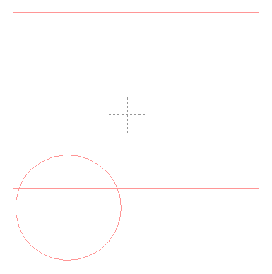
Image 1: An outline figure consisting of two drawing elements
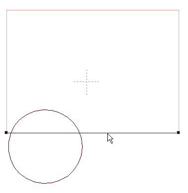
Image 2: Highlight the elements subtending to each other ([Shift]+[M1])
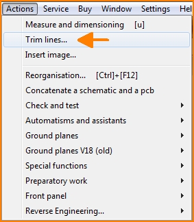
Image 3: Select option "Trim Lines..." in Menu Actions
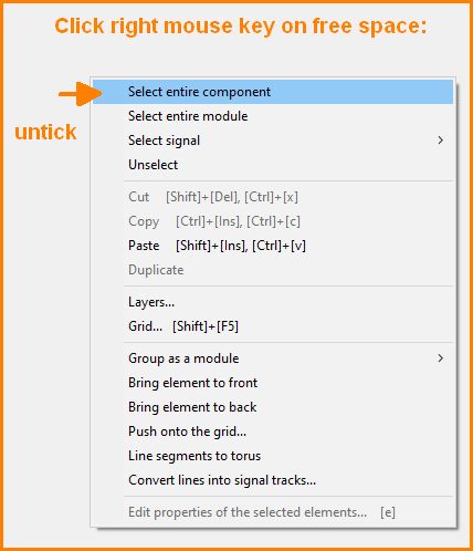
Image 8: Context menu: Untick line if ticked
Shift lines
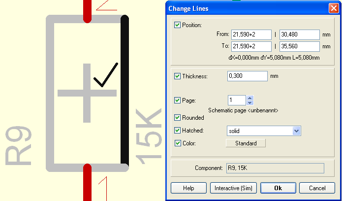
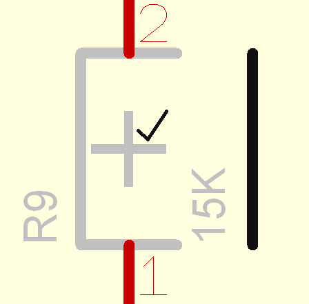
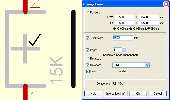
If you double click on a line the dialog "Change lines" opens. You can shift the position of the lines by giving an add or a subtract command in the coordinate box. The following image shows how to shift a line 2mm to the right side. Double click (M11)upon the line and see the following dialog:
In case a single click on the line always highlights the whole package, please release button ![]() which is located in the sidebar on the right. Now enter the values "+2" to the x-coordinates of the start and end points of the line.
which is located in the sidebar on the right. Now enter the values "+2" to the x-coordinates of the start and end points of the line.
Result:
If you now again doubleclick the shifted line, the modifications of the coordinates are overtaken.
.


