FAQ: Handling in general
Contents
- 1 I am wondering if there is any possibility to export settings from Target 3001! to a file and import it to a new installation of the program after system refresh?
- 2 The buttons in the menu bar dont stay depressed so I don't know what mode I am in. Any help?
- 3 Rotating multiline text
- 4 The placing of packages with the autoplacer takes too long. I have activated airwires.
- 5 I have placed all components in the schematic but cannot find the power supplies of the IC. Are all power supplies automatically connected?
- 6 The printing of a schematic takes too long time. What am I doing wrong?
- 7 The signal "GND" is correctly connected, but still after "Check" the following error message apears "Signal unfinished: GND"
- 8 "Power without supply: GND" and "Island without Ref-Pin: SIG$23" after the use of the function "Check"
I am wondering if there is any possibility to export settings from Target 3001! to a file and import it to a new installation of the program after system refresh?
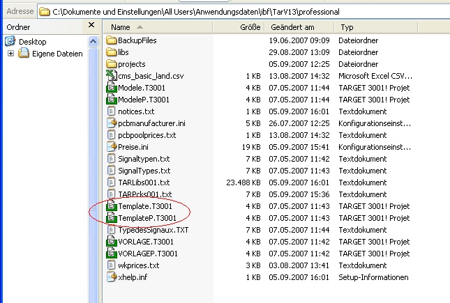
Please have a look on your PC in the directory C:\Documents and settings\All Users(or different)\Application Data\IBF\TarVX\smart (or different). There you will find template projects.
For the English version:
Template.T3001 (for projects "Layout with Schematic") and TemplateP.T3001 (for projects "Layout without Schematic"), see image:
Where templates are located...
For the German version:
VORLAGE.T3001 (for projects "Layout with Schematic") and VORLAGEP.T3001 (for projects "Layout without Schematic")
For the French version:
Modele.T3001 (for projects "Layout with Schematic") and ModeleP.T3001 (for projects "Layout without Schematic")
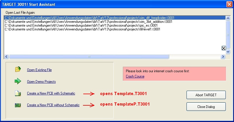
According to your language version those projects are taken as a default (template) always when you begin a new project.
The "Start Assistant" uses those templates...
If you would take one of your personal projects having a preferred setting, rename it to Template.T3001 or TemplateP.T3001 and overwrite the files in the directory mentioned above. Then those ones will be opened after choosing from the Start Assistant. But this way might be a bit laborious. Easier it would be if you would save your preferred projects having the desired settings in an empty state to a separate directory called lets say "Defaults". Any time you wish to start a new project having certain settings, open one of your personal default projects by the "Open Existing File" option and start working. I think that is the quicker way. A genuine function for transferring settings as a whole to another project does not (yet) exist in TARGET3001!
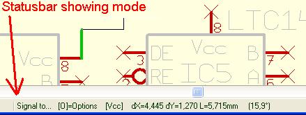
Just have a look at the status bar below. This always shows the mode you're in and tells you some options you can take:
The status shows which mode you're in
Rotating multiline text
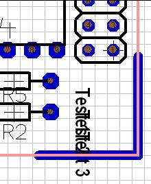
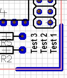
The line feed of multiline text when rotated at 90 degrees is only in y-direction, not in x-direction. The effect is that the text-lines overlay each other:
How to overcome this?
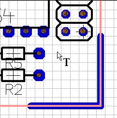
Open the Text tool:
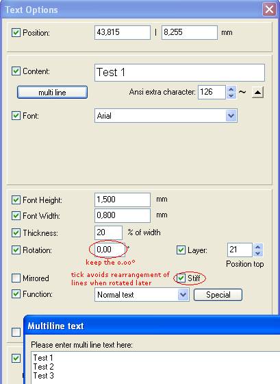
Write each text line within the multiline tool but don't give rotating advice in the dialog:
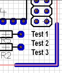
See the result:
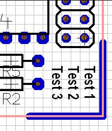
Now select the three lines by [Shift]+[M1] or by opening a highlighting square over them. Press key [t] for "turning" in 90° steps counter clockwise. The turning center is the cursor position! If you want to turn at a different angle, please use [Shift]+[t] and enter to the appearing dialog. The result might be:
Remark: if you don't tick the box "Stiff" in the text dialog, the turning/rotating follows normative aspects (the sense of the rotation is kept but the alignment of the textlines is different):
.
The placing of packages with the autoplacer takes too long. I have activated airwires.
Switch off airwires in "LAYERS" tool (No. 27). TARGET has to compute every airwire, after each placing. This takes too much time.
I have placed all components in the schematic but cannot find the power supplies of the IC. Are all power supplies automatically connected?
No. The power supplies of some of the IC must be inserted and placed by the function "import rest of components" in the COMPONENTS menu. Place all supply connections with the corresponding blocking capacitors and a plug on a free area of your schematic (or on a new schematic page) and then connect them with the reference symbols for "VCC" and "GND".
The printing of a schematic takes too long time. What am I doing wrong?
Please use WINDOWS fonts.
The signal "GND" is correctly connected, but still after "Check" the following error message apears "Signal unfinished: GND"
Although the signal GND visibly might appears to be correctly connected, there must be a disconnection. Set the selection mode "mark hitten signal island" and select each of the signal islands with a mouse click (left mouse button). You aöso might inspect your layout in x-ray view for misconnection (toggle the hash key [#]).
"Power without supply: GND" and "Island without Ref-Pin: SIG$23" after the use of the function "Check"
- "Power without supply: GND"
TARGET has recognized that one or more connections to components of this signal trace with function "Power", but TARGET could not find any connection pin with the function "Supply". Choose this function for a connection pin of a plug-and-socket connector, because the signal "GND" is externally connected to your circuit e.g. by a socket or a receptacle.
- "Island without Ref-Pin: SIG$23"
This is a fatal error of the circuit check and must not be ignored. It can appear, for example, after the insertion of a resistor into a existing signal trace or if both connections of the resistor are connected to the same signal. TARGET recognises two islands of the signal "SIG$23", which would be short-circuited by the autorouter in the PCB. Each of the signal islands must be connected with a reference-symbol or with a bus (which has the same function as a ref.-symbol) e.g. when distributing a signal to another schematic page.


