Creation of a 3D Model
Contents
Preface
The creation of a 3D-model in TARGET 3001! is very simple. It follows a few rules which anyone with normal visual imagination can follow. Basically it is nothing else than joining different geometrical figures in space. The syntax needs only few basic figures: a solid (S), a cylinder (C), a torus (TX, TY, or TZ), an extruded Polygon (E) and lettering (Text, TT). Lettering is always plain.
General flow
The creation of a 3D model has the following progress:
- Loading of the footprint from the component library (thus the existing of a component's land pattern is needed).
- Creation of the component's body according to the datasheet.
- Creation of a component pin according to the datasheet.
- Multiplication of the pin.
- Lettering.
Modelling a DIP 8 package model
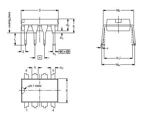
We now want to create a 3D model for a DIP 8 package. We use the following datasheet: dil8.pdf. It's the same we used when drawing the footprints.
These are the main views:
Please also have a look at the syntax of the 3D-editor here:
3D-Syntax_e.pdf
You should have it on your desk (see previous chapter also).
Here is a 3D model missing...
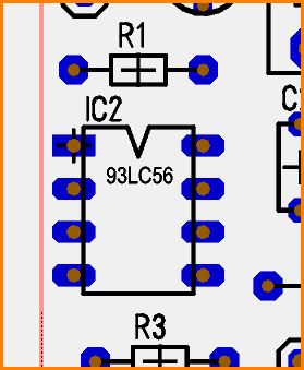
If we have a look on the unrouted project PIC_3D.T3001, found here: pic_3D.t3001 we focus on the IC2 with value 93LC56. It has a "DiP8_without_3D-model" housing from the current library Standard.PCK3001. If you do not have this housing at your disposal, please just delete the syntax in the 3Dview. You might abstain from saving this deletion in case you don't have the time to work this course through completely...
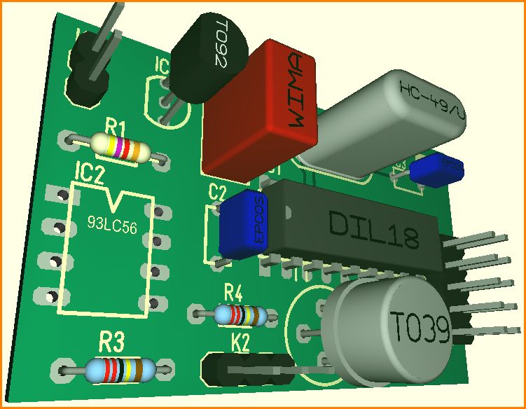
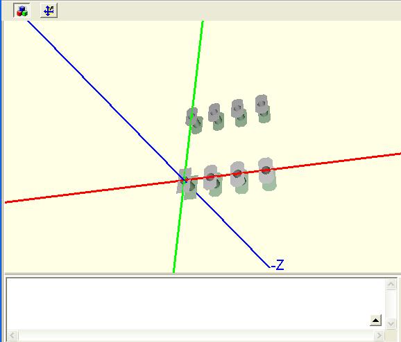
Loading the 3D-view (menu "View/3D-View") we see the following:
This component does not have a 3D model. What we see is a simple extrusion of the plain view by 1mm as it is given as a standard to any non-3D-modeled component. Now we want to create a 3D model for this DIL8 housing.
Load the soldering pattern from the library
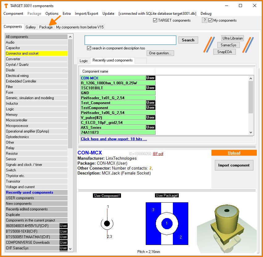
In a project "Double sided PCB with schematic", open the component browser (= the component database) in the schematic view by ![]() or the keyboard key [Ins].
or the keyboard key [Ins].
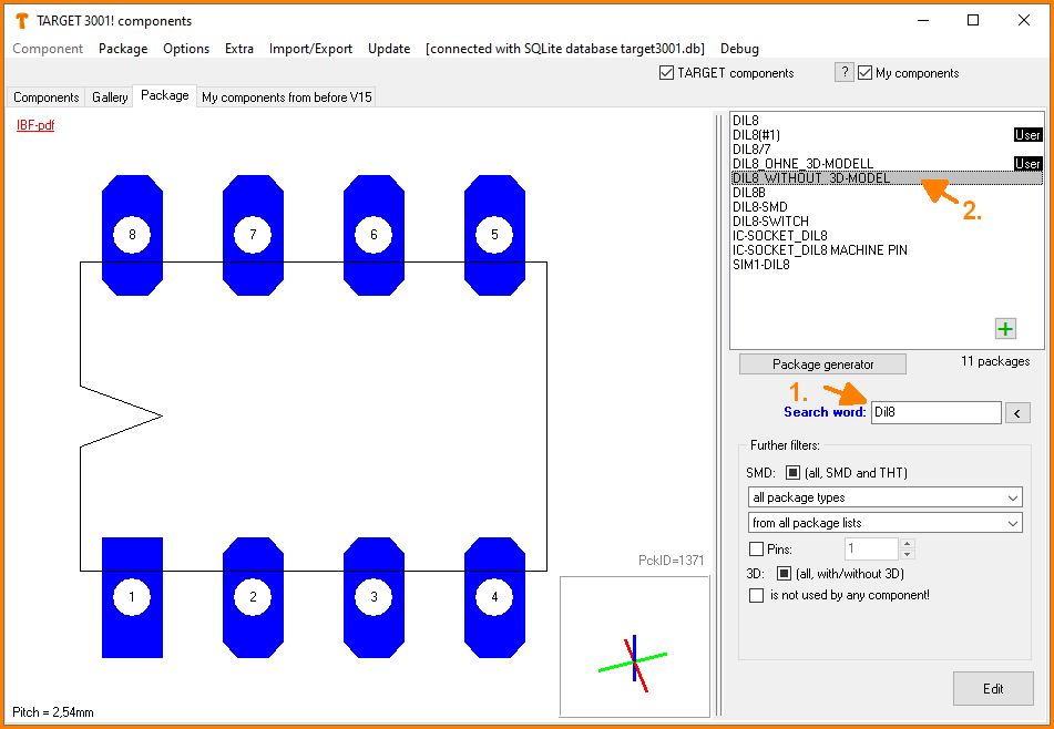
You will see this image:
.
Click on the tab "Package" (arrow) to get the view of the package selection. Here you can have any solder pad pattern presented to you. In our example we use the DIL8_WITHOUT_3D-MODEL.
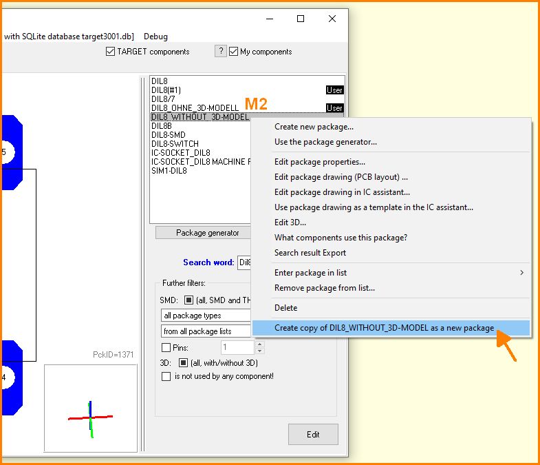
Before you can create or modify the 3D model of a TARGET original component, you must create a copy of the component. To do this, click
M2 on the component name and select the option Create copy of DIL8_without_3D-MODEL as new package.
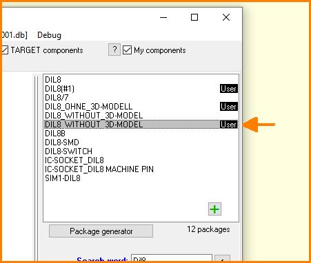
The copy of the TARGET component then becomes a user component and can be freely edited:
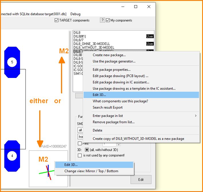
To edit the 3D model there are two possibilities, either right click on the rotating coordinate system or click M2 on the part name. In both cases select the option "Edit 3D..."
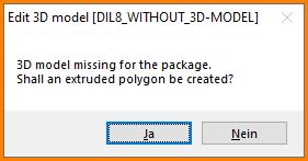
Now the 3D model editor is opened and can be created/edited. If an enclosure does not have a 3D model yet, you will be asked beforehand if you want to create an extruded polygon.
An extruded polygon is just a "pulling up" of the package outline. In most cases, the result is a simple cuboid that gives a good impression of the body. If you answer no, which you should do for the rest of this example, the outline and the pattern of the soldering pads appear and the creation of the 3D model can begin.
3D Footprints
The red is the X-axis, the green is the Y-axis, the blue is the Z-axis, each in positive as well as negative direction. This package has its absolute zero congruently to the center of pad # 1, where the handle cross is located. This can be so, but it is no "must". The relevant point is absolute zero, wherever it is located in the package layout.
Middle axis - what?
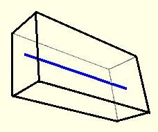
A solid and a cylinder in 3D view are constructed by a middle axis with a starting point and an end point somewhere in space. This middle axis is widened by a value "width" and a value "height" respectively a value "diameter". For a simple cuboid this middle axis might look like this:
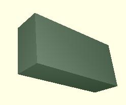
If you see this wired model completely skew, please have a look at this coated version:
The length of the body is defined by the blue middle axis (M=15mm), it's width is 7mm and the height is 4mm. The construction of this body begins with the localization of the starting point and the end point of the middle axis each defined by X-Y-Z coordinates.
Now we need the data sheet to fix the dimensions of the body relative to the drillholes of the pads. The center of pad 1 is on X|Y|Z = 0|0|0 so the housing begins in the negative X-area, according to the datasheet at -Z =-1,15 mm (all further measurements are meant in mm). The X coordinate of the starting point of the middle axis shows -1.15.
The Y-value is positive. It is to be calculated by half of the width of the body plus the distance of the pin to the body. We can take half of the e1 value of the datasheet and get an Y coordinate of 3.81.
The Z coordinate we also take from the datasheet by the half of A2 plus the distance A1. The result is: 0.5*3.2 +0.51 = 2.11. The starting point of the middle axis thus has the coordinates: -1.15|3.81|2.11 We enter these values to our first editor line:
We write: S-1.15,3.81,2.11
Please note: S stands for "Solid" (=cuboid). This indicates to the editor that all further entries to this line are meant for a solid. Decimals are separated by a dot. A comma divides the coordinates resp. all other measurements.
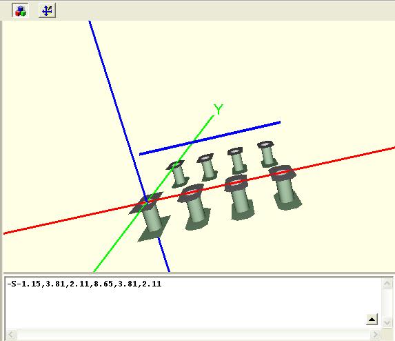
In the 3D view we see nothing because we have defined only the starting point of the middle axis. Now we want to fix its end point. The X-value is calculated by -1.15 + the length of the housing (the distance D of the datasheet). D shows 9.8 mm so the value is: -1.15 + 9.8 = 8.65. The Y-value equals the first Y-value, thus 3.81, The same with the Z-value, it is 2.11.
We add those values to the syntax line so that it looks like: S-1.15,3.81,2.11,8.65,3.81,2.11
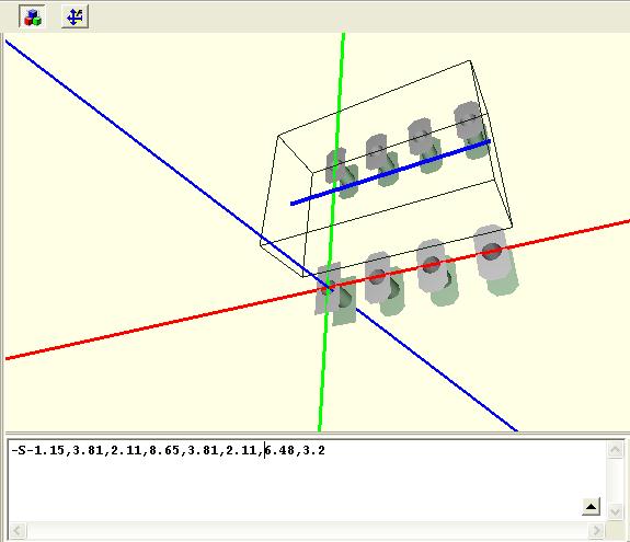
The middle axis can be seen now. But first we have to add a - (minus) in front of the S. This is to tell the viewer that we want to have the body visualized like a wired model (= transparent, showing only outlines). Please note: there is no comma behind the S:
Width and height of the body
Now we only need to enter a value for width and height of the body. According to the datasheet the width equals E=6,48 and the height equals A2 = 3,2. We enter those values in correct writing and get:
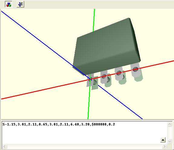
We choose a nice color, let's say $888888 and add a champferradius 0,2 We delete the "-" in front of the S and now can see our solid in the end-version:
We can watch it from all sides now. Click into the canvas, hold the mousekey and move it.
Creating the leads
Now the pins (leads) are still missing as well as a lettering. We are going to construct a pin out of three solids and one cylinder. Then we copy it. That means the cross section of our pin will show a square. The fact that the pins at the corners of the body have a different shape than the others won't bother us. We also ignore the fact that the pins narrow after coming out of the body.
Create one pin
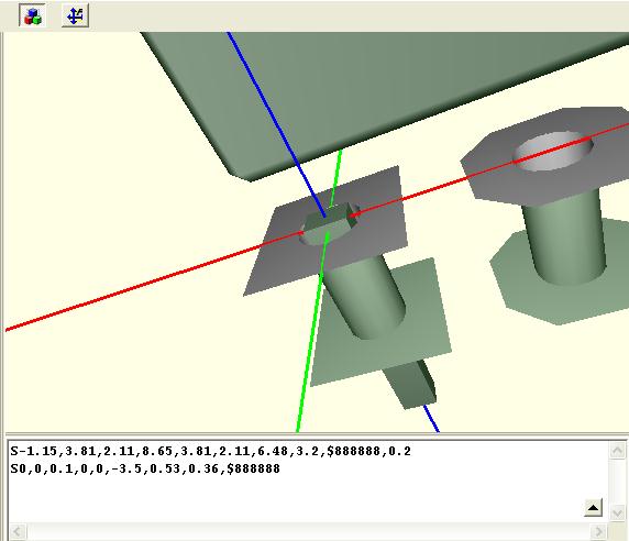
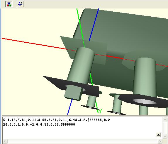
Let's begin with the pin located in the origin. We want to define the first solid, it is the part of the pin, which sticks in the drillhole. We begin with the starting point of the middle axis ad place it 0.1mm higher than the board surface for giving a bit space. The middle axis must dive into the board according to the datasheet with a length of 3.6 (-0.1) mm. The syntax looks like this: S0,0,0.1,0,0,-3.5 For the fact that we start a new body, we begin with a new line. The width we choose according to the datasheet with b1 (=0.53). The height we select c (=0.36). We use the color $888888, we pass on a chamfer radius.
The syntax now looks like this: S0,0,0.1,0,0,-3.5,0.53, 0.36,$888888
In the 3D editor we see the following picture:
It's up to you whether to cut off the part of this body which protrudes from the bottom of the board or not. For this example we cut it off and set the end-point of its middle axis to -2.0.
Syntax: S0,0,0.1,0,0,-2.0,0.53, 0.36,$888888
In the 3D view this effects the following:
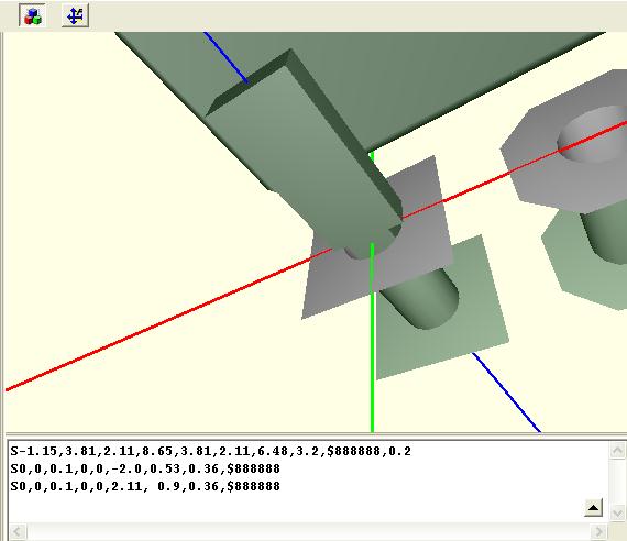
Now we want to create the upper part of the pin which we draw for reasons of simplifying just a bit wider than the "drillhole" one. The syntax looks like this: (same middle axis beginning from Z0.1 and reaching exactly to the middle of the height of the housing (=0,5*A2+A1) which equals 0.5*3.2+0.51= 2.11. The width is 0.9 and the height is 0.36. The syntax is:
S0,0,0.1,0,0,2.11, 0.9,0.36,$888888 and the view shows:
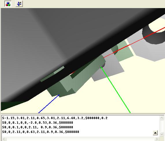
The next step is to create the emission of the pin from the body. We place the middle axis orthogonally to the end point of the previous axis:
S0,0,2.11,0,0.63,2.11,0.9,0.36,$888888
The emission of the pin into the body of the housing is a bit too long but we don't mind that.
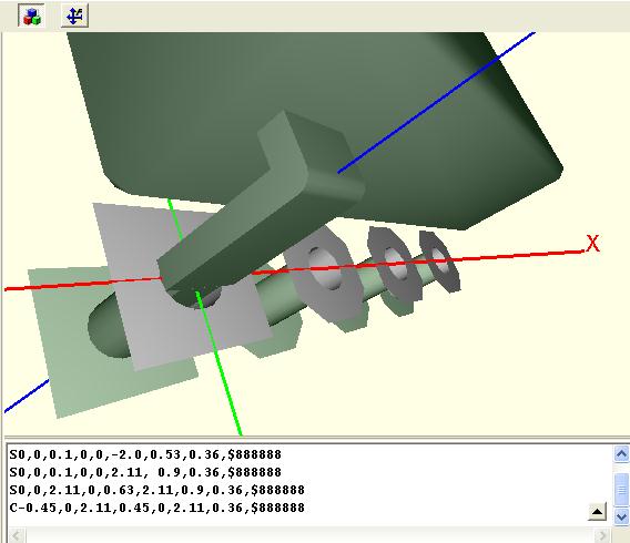
Now we only need this rounding at the bending of the pin. We just place a cylinder with a middle axis along the inner corner of both of the bodies. The radius equals the thickness c of the pin: 0.36.
C-0.45,0,2.11,0.45,0,2.11,0.36,$888888
Copy this pin by the pitch
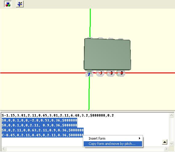
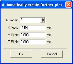
Now we are going to copy this pin three times by "pitch-distance". We highlight the pin syntax and press the right mousekey. The following dialog appears:
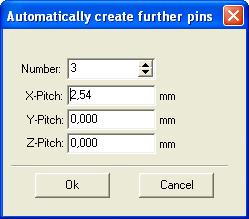
We select "Copy form and move by pitch". Another dialog asks us for the direction of the movement and the pitch ( e =2,54). We enter the data:
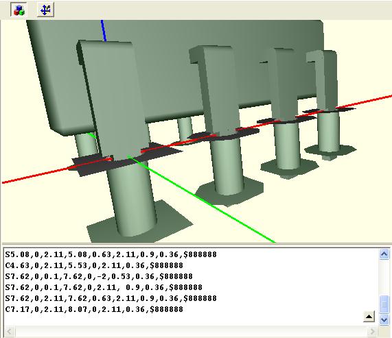
This is what we get:
Copy the row to the other side
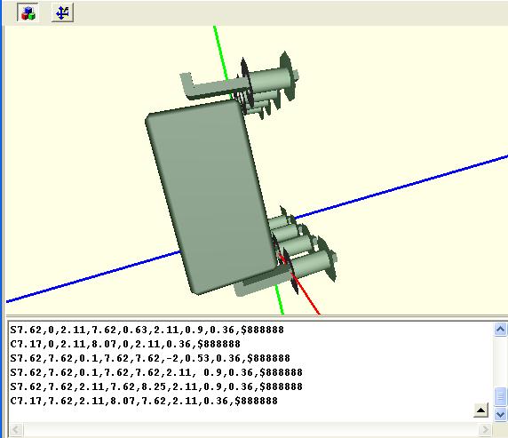
Now we have to copy this row to the other side. We begin copying the last pin by Y-direction by the value e1 =7.62. We ignore the fact that this offset is not the "pitch" though the dialog says so.
We receive:
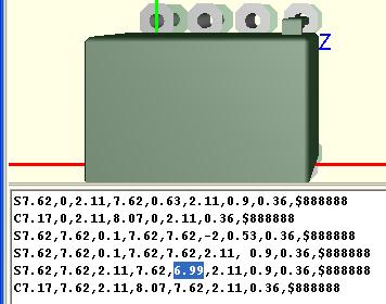
We must change the bending of the pin into the opposite direction by changing the syntax:
S7.62,7.62,0.1,7.62,7.62,-2,0.53,0.36,$888888 S7.62,7.62,0.1,7.62,7.62,2.11, 0.9,0.36,$888888 S7.62,7.62,2.11,7.62,8.25,2.11,0.9,0.36,$888888 C7.17,7.62,2.11,8.07,7.62,2.11,0.36,$888888
The third line was responsible for the emission of the pin from the body. So we must reduce the Y-offset value we just used (7.62) by 0.63 so dass sich the value 8.25 reduces to 6.99 reduziert:
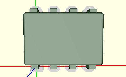
This pin now needs to be copied three times in negative X-direction the same way we have just learned:
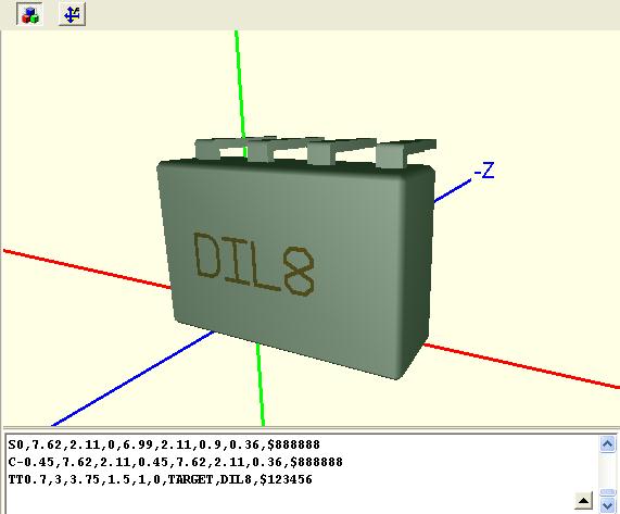
This is the result:
Lettering
Now we add a nice lettering and we are done.
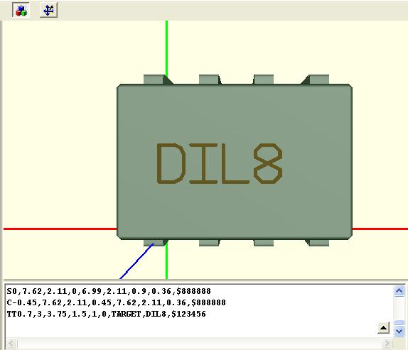
Text always begins with TT or by the word "Text". Then follows the definition of the starting coordinates X,Y,Z of the first character (bottom left of it). Further entries are Height, Width, Angle, Fonttype, Contents, Color. You will notice soon that it is helpful to play a bit in this respect. For our lettering we choose syntax: TT0.7,3,3.75,1.5,1,0,TARGET,DIL8,$123456
The fonttype is TARGET and the Content is "DIL8".
It might be helpful to let the body be displayed in wired outline (- in front of the first row "S"). It might be the case that your lettering is a bit too low and thus can be covered by the coating of the body.
Saving the model
By using the "Save" button we assign this model as a property to the chosen component. Fortunately there is is no separate 3D model library in TARGET 3001!.
You might consider to use a different color for the body to deviate from the color of the pins. For instance $333333 - but this is up to you.
The complete syntax is:
S-1.15,3.81,2.11,8.65,3.81,2.11,6.48,3.2,$888888,0.2
S0,0,0.1,0,0,-2.0,0.53,0.36,$888888
S0,0,0.1,0,0,2.11, 0.9,0.36,$888888
S0,0,2.11,0,0.63,2.11,0.9,0.36,$888888
C-0.45,0,2.11,0.45,0,2.11,0.36,$888888
S2.54,0,0.1,2.54,0,-2,0.53,0.36,$888888
S2.54,0,0.1,2.54,0,2.11, 0.9,0.36,$888888
S2.54,0,2.11,2.54,0.63,2.11,0.9,0.36,$888888
C2.09,0,2.11,2.99,0,2.11,0.36,$888888
S5.08,0,0.1,5.08,0,-2,0.53,0.36,$888888
S5.08,0,0.1,5.08,0,2.11, 0.9,0.36,$888888
S5.08,0,2.11,5.08,0.63,2.11,0.9,0.36,$888888
C4.63,0,2.11,5.53,0,2.11,0.36,$888888
S7.62,0,0.1,7.62,0,-2,0.53,0.36,$888888
S7.62,0,0.1,7.62,0,2.11, 0.9,0.36,$888888
S7.62,0,2.11,7.62,0.63,2.11,0.9,0.36,$888888
C7.17,0,2.11,8.07,0,2.11,0.36,$888888
S7.62,7.62,0.1,7.62,7.62,-2,0.53,0.36,$888888
S7.62,7.62,0.1,7.62,7.62,2.11, 0.9,0.36,$888888
S7.62,7.62,2.11,7.62,6.99,2.11,0.9,0.36,$888888
C7.17,7.62,2.11,8.07,7.62,2.11,0.36,$888888
S5.08,7.62,0.1,5.08,7.62,-2,0.53,0.36,$888888
S5.08,7.62,0.1,5.08,7.62,2.11, 0.9,0.36,$888888
S5.08,7.62,2.11,5.08,6.99,2.11,0.9,0.36,$888888
C4.63,7.62,2.11,5.53,7.62,2.11,0.36,$888888
S2.54,7.62,0.1,2.54,7.62,-2,0.53,0.36,$888888
S2.54,7.62,0.1,2.54,7.62,2.11, 0.9,0.36,$888888
S2.54,7.62,2.11,2.54,6.99,2.11,0.9,0.36,$888888
C2.09,7.62,2.11,2.99,7.62,2.11,0.36,$888888
S0,7.62,0.1,0,7.62,-2,0.53,0.36,$888888
S0,7.62,0.1,0,7.62,2.11, 0.9,0.36,$888888
S0,7.62,2.11,0,6.99,2.11,0.9,0.36,$888888
C-0.45,7.62,2.11,0.45,7.62,2.11,0.36,$888888
TT0.7,3,3.75,1.5,1,0,TARGET,DIL8,$123456


