

Simulation pitfalls
Please take some seconds for this article.
You should not be untroubled by these traps.
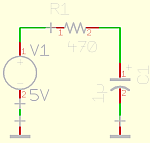
- Powersymbols
 do not supply any voltage! You have to connect a voltage source to your e.g. +5V circuit.

- FALSE: My circuit includes alternating (sinusoidal) current sources
 , so i have to apply an ac-analysis.

It is quite simple:
My abscissae (x-coordinate) of the oscilloscope shall be the time => Transientanalysis
My abscissae (x-coordinate) of the oscilloscope shall be the frequency => AC-Analysis
My abscissae (x-coordinate) of the oscilloscope shall be a voltage => DC-Analysis
- Not connected components (a tiny red cross indicates the error)!
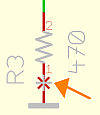
Pins are connected via (green) signal lines; so do not simply join pins.

- I do not see any rc charge curve?
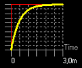
Only if you select (default) in the transient analysis dialog, then the curve will be there.


- What is a capacitor? What a dull question! Edit capacity value and play up simulation: Oops, what's that? The simulator shows (apparently) absurd curves or error messages. Result of a fallacy! You apply only a model of the capacitor. Surely you can use a very ideal capacitor model, carrying only the capacitance as quantity, but: A model which is closer to a real capacitor has an additional serial resistor, so that e.g. charge-time/current-peaks of a unit step input response
 do not get arbitrary small/high values. You should ever ask yourself:
Is my model of this component too ideal for my application case?

Further Details:
Supply
1) A reference symbol is only a drawing aid. It allows to design the schematic in a well arranged manner and to spread the circuit over multiple sheets.
2) What should +5V stand for? Is it a 1W (one watt) or a powerfull 100W source? Your circuit would work fine with an ideal source, but your real application could suffer power stability showing bizarre effects.
Types of simulation analysis
The selection of the appropriate analysis do not depend on the sources that your circuit contains. You will find further graphical explenation in the respective analysis dialogs.
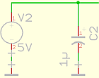
Initial conditions
The simulator has to find a first bias point (solution) for time t=0. Some components are provable with an initial state: e.g. you can define that a capacitor is charged to 5V at time t=0. If you do not select "Use initial condition" then the simulator will calculate only one (initial)solution of many with any initial states of the capacitors etc.; viz. the steady state, that is after all capacitors in your real application are settled.