Clipboard
The clipboard is meant for duplicating parts of the schematic or to copy it to other applications (MS-Word, OpenOffice etc.)
Contents
Copying within TARGET 3001!
Subassemblies, which might be used in several designs can be seen as a kind of "multi element" (e.g. a power supply). So you would like to insert them as a group instead of creating them new each time. How do you do that? After having drawn a schematic and a layout of such a subassembly copy it to the clipboard and paste it to a new, empty project. Schematic first, then the layout. Save this project under a reasonable name. Later open this new project again and pick the assembly from it. Paste it to your desired design, schematic first, then the layout.
An example
A symmetrical universal power supply powersupp_univ_sym.T3001
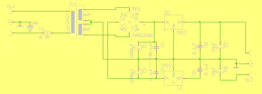
Image 1 shows the schematic of a symmetrical universal power supply
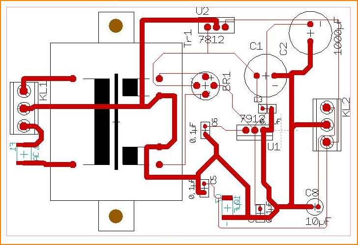
Image 2 shows a layout of it.
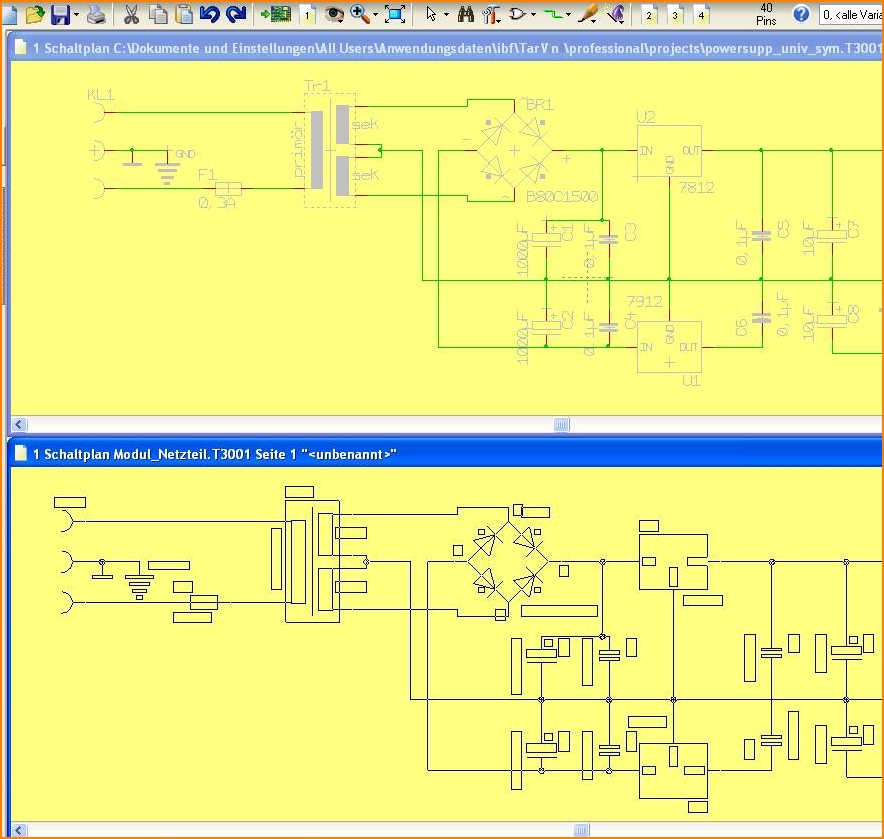
Now open an empty project and tile the window horizontally. Now take the complete schematic of the module to the clipboard. For doing so drag a Catch window over the complete figure and press [Ctrl]+[c].
Image 3 Now paste the clipboard by [Ctrl]+[v] to an empty schematic page.
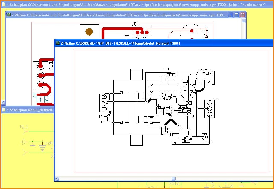
Image 4 Do the same with the layout.
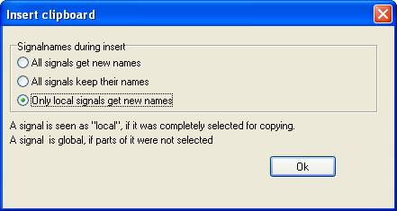
Prior to pasting the clipboard to a new schematic or layout the dialog "Insert clipboard" opens. You get asked what to do with the signal names. If you use the default setting, all "local" signals get renamed when pasted. "Local" are those signals being taken completely to the clipboard. So the signal Sig$8 is going to be renamed Sig$18, at the second pasting it gets renamed Sig$28 and so on. This is the dialog mentioned:
Copy several "channels"
You want to create a circuit that consists of 3 "channels", i.e. three parts of the circuit are identical, only some parts of the control logic appear only once.
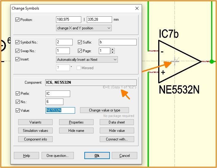
First draw a channel, if necessary also in another project file as a reusable template. Draw the circuit diagram and the corresponding board layout! Now copy the circuit diagram part into the target circuit diagram. In our case, twice. Then promptly copy the corresponding package and tracks into your target layout. Also twice. A symbol in the schematic, for example, then knows: I am the 1st or 2nd copy of IC17. The corresponding package then also knows this and the two are connected to each other.
When asked about the signal names, it is best to select the last option: Only local signals get new names.
Please DO NOT REORGANISE between copying, as this will erase the copy-from information.
Alias: channel, modules, channel, group, hierarchy, multichannel, replication, reuse, room
Displace parts of the schematic to another schematic page
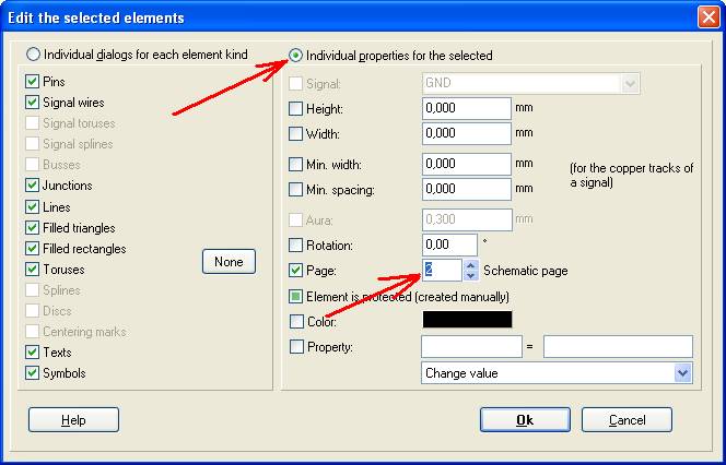
In case you are in need of more space for the schematic and thus need to split it into two pages, then please do not use the clipboard-copy and paste. The better way is to highlight the section in question and move it by the use of the [e] key dialog to a desired schematic page:
The highlighted elements disappear from the source page and are now placed upon the target page. Please have a look that the target page either is completely empty or that at least this part of it where schematic part shall be inserted is free. In case you have intermixed parts of the schematic the easiest way of "repair" is the use of the undo function and better arrangement within a new trial.
Copying to MS-Word, OpenOffice, CorelDraw ...
You can easily copy and paste a schematic to any other program which is able to handle vector graphics (GDI WMF, Graphics Device Interface, Windows Meta File). Such programs are for instance: MS-Word, OpenOffice or CorelDraw. Pixel based programs like IrfanView see below. Vector graphic can be scaled (enlarge or reduce) nearly without any loss.
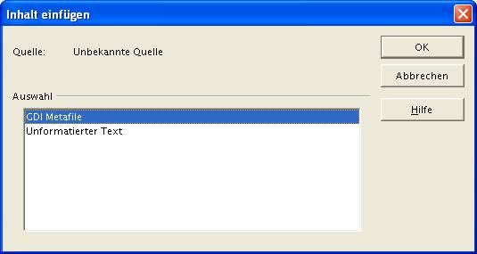
First highlight and copy the desired parts of the schematic to the clipboard. In the programs mentioned use menu "Edit/Insert":
Otherwise Word or OpenOffice uses unformatted text showing just the netlist, when only pasting by keys [Ins] or [Ctrl] + [v] .
Copy bitmap images (BMP)
For transferring pixel based images to other programs like IrfanView or similar you can not use the copy function. You need to use the Windows - screendump/screenshot function: press key [Print] from your keyboard. Now the complete screen including the visible part of your schematic gets copied to the clipboard. In IrfanView you might expose the part in question.
IrfanView (e.g.) is a pixel based program. It has no vector graphic providing lossless scaling. The resolution is restricted by the screen-resolution. In case you need higher resolution you might use the TIFF-Export (to be found in the printing dialog). A TIFF is also pixel based and can be opened with IrfanView.
Copying a netlist
Highlight a certain part of your schematic and copy it to the clipboard. If you use the function "Insert from Clipboard" in any word program you get the netlist of all components involved.:
BR2	0001	"5V"
BR2	0002	"Nin"
BR2	0003	"GND"
C1	0001	"OUT_R/C"
C1	0002	"Loud"
D1	A	"GND"
D1	K	"5V"
F1	0001	"L_in"
F1	0002	"2"
F2	0001	"1"
F2	0002	"Nin"
G1	1	"Sig$17"
G1	2	"Sig$18"
The line syntax is:
Component name TAB Connection number or name TAB Signal name in quotes.


