Symbol generator
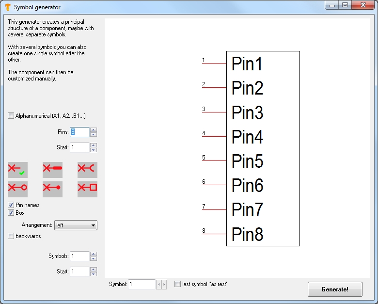
The symbol generator is part of the component editor which had been issued with version V18. Please find it in schematic menu Components/Special functions/Symbol generator. It eases the creation of symbols with many pins. It supports the creation of symbols with multiple gates (sub-symbols) as well. Each symbol-as soon as created-can be edited later independently from the functions of the generator. The Symbol generator opens in following view:

Image: The Symbol generator in default setting.
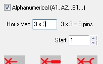
The pins can be named numerically or alphanumerically (e.g. if you want to name the pins according to the pads of an BGA component like a matrix). In the second case, tick the box at "Alphanumerical (A1, A2... B1...)".

Box "Alphanumerical" (A1, A2... B1...) ticked.
Set the overall number of Pins. This figure should include all sub symbols (gates) if there are such.
Start means the cipher of the initial pin which not necessarily needs to be 1.
Now select the shape a pin shall have: neutral, male, female, ring, dot or box. The little green tick signals the alternative currently chosen. Except the first none of them requires normally a pin name or a box around it. If you nevertheless want such, you need to tick the boxes again after you had chosen its shape.
If Pin names shall be visible besides the Pin number tick the box. If the symbol shall be surrounded by a rectangular Box, put a tick here. The Arrangement of pins can happen: left, two sided, alternating (= zigzag) and all around. In general the number of the first pin is located top left, while the row continues counter clockwise. If you tick the box backwards pin 1 starts top left while the row continues clockwise.
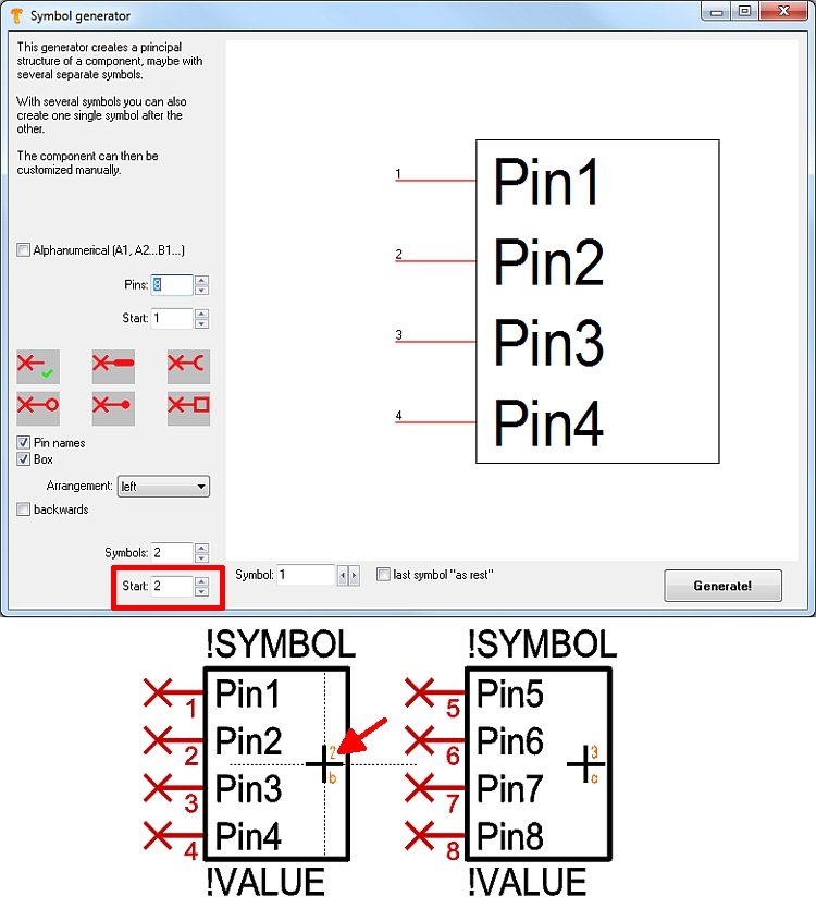
Symbols means the general number of subsymbols of the component. Which subsymbol you currently see on screen please see in the lower part of the dialog, in the box Symbol. The box Start defines with wich subsymbol the row of subsymbols will start. If you enter e.g. 2 here, the row of subsymbols starts with the second subsymbol.

Image: After "Generate" the row of gates starts at 2. It might be that gate #1 looks completely different so that you like to draw it by hand later, independently from this generator.
Sometimes you wish to define the power supplies separately - in TARGET terminology - as "rest". Now tick the box last symbol "as rest". Now when generating the whole symbol the last sub symbol will be furnished with Rest-properties. That means later, when importing the symbol with all its sub symbols the rest is not subsequently inserted. It needs to be inserted by separate action using menu option Components/Insert rests of components...

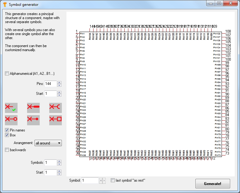
Image: The symbol generator gives e. g. a symbol with 144 pins.
What about the function of the pins, represented by the pin names? Please take advantage of editing pin names in a text editor.

