Grid
General
Open it by ![]() underneath
underneath ![]()
Or Menu View / "Grid"
The grid is the important placement aid which should be used to reach exact placement of packages and tracks. It also is crucial to establish connections of signal Tracks to pins/pads properly. Also the drawing of components is easier when using a grid. Never switch off the grid! Sure you can do it but you shouldn't. The question which unit (metric or imperial, millimeters or mil, meters or inch) shall be used in the complete project is set in the grid dialog.
The grid value in the schematic shall remain at 25 mil which is 1/40 inch which is 0.635 mm. It is because all of the TARGET 3001! components are based on this grid. "cursor snaps on grid [F6]" should also remain activated in the schematic!
In the PCB layout you may use different values, for example for SMD componnents 4 mil which is round about 0.1 mm. Smaller grids normally are not reasonable. If you have to hit off-grid items, please type key [+] to catch the coodinates.
The Grid-Tool
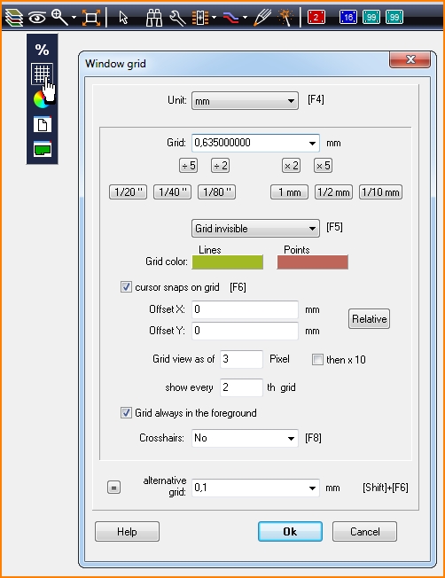
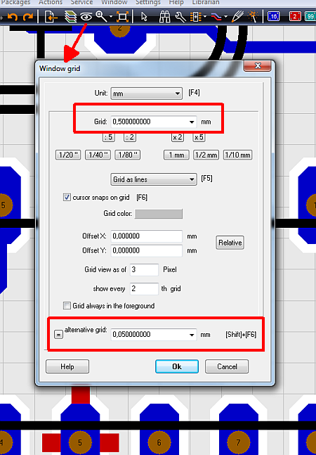
You can select the appropriate length unit: Inch ("), mil, µm and mm. (1 inch = 1" = 25,4 mm; 1 mil = 1 thou = 1/1000" = 0,0254 mm). Each value between 0,001 mm and 10 mm can be entered as a grid value. The value doesn't need to be dividable by 0,001 mm (for example: 0,378512769). The grid can be displayed either as lines,as points or invisible. A grid set invisible is not turned off. Depending on the "cursor snaps on grid" entry, the 90° cross hair cursor snaps on the grid. The distance of the grid reference point to the absolute zero coordinate (Abs 0|0) is set by the Offset X/Y values. This is an advantage if you e.g. need to place a connector on a metric euro-size-PCB (160 x 100mm) exactly at the small side where the grid unit is set to inch.
"Grid view as of" means that the grid is only displayed if between the grid points on screen there is minimum the amount of pixels set. This protects the computer to fill the screen with grid lines or points which makes it difficult to be separated from each other. Ticking "Then x 10" does the same when zooming out far. You can also decide here, if TARGET should draw each grid point or show every 2nd or 4th or whatever. The following settings have proved to be good: Grid: 0,635mm = 1/40, invisible, cursor snaps on grid, Offset X/Y = 0/0, Grid view as of 3 pixel, show every 2nd grid.
Relative- button: If you set a relative origin (key [Pos1] or [Home] at cursor position), the absolute grid is still used. Only if you press the "Relative" button the grid will refer to the relative origin. If you press the [Pos1] or [Home] key twice, the absolute zero is used again and accordingly the absolute grid. In case you still have a weird offset then please delete it fromn the dialog.
Decide, whether the grid should be in the foreground or in the background by ticking the box.
Crosshairs:' Either a 90° cross or an additional 45° cross can be added. While layouting: Press functional key [F8] multiple times to toggle the modes.
During the layout process it might be good to have an alternative grid of a different width you can easily switch to. Set the alternative value in the dialog and toggle between both grids using the [Shift]+[F6] key see below...
Package not on the grid
see Layout Menu Actions/Push onto the grid...
It can happen, that package components not are placed exactly to the grid. Push the package to the closest point of the grid using this function.
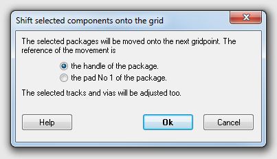
Pad No. 1 or the handle of the package can be taken as reference point regarding displacement. Anyway the component is moved less than one grid step in X- and Y-direction.
Autorouter result not on the grid
The auto router itself does not use a grid while autorouting. If you later have a part or a segment you'd like to have on the grid, push it to the grid.
Example:
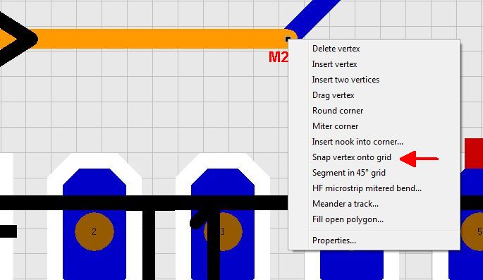
The following grid is 0,5 mm, set after the routing to make it weird. The orange colored track is highlighted, little black touchpads (vertices) are visible at the end.
Right mouseclick (=M2) upon one of the black vertices opens a context dialog from which you choose option "Snap vertex onto grid".
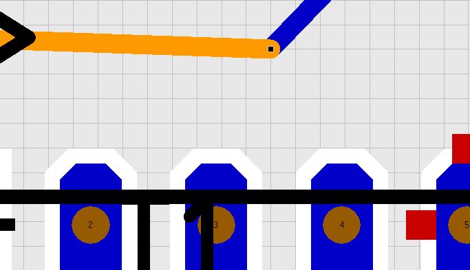
Result:
The same you can do with components: M2 upon handle, similar dialog...
Alternate grid values
In order to use an alternative grid value quickly within a project during your design work you can use the short key [Shift]+[F6]. Prior to it you should have set the alternative grid value in the grid dialog:
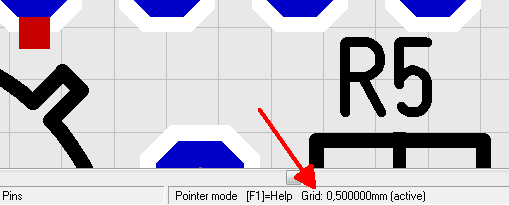
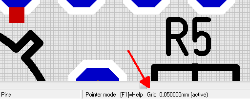
Which grid value you currently are using please see in pointer mode on the bottom of your screen:
After pressing [Shift]+[F6]:
Snap point
Please see here: Snap Point
Alias: move offset metric


