Gerber
General
If you want to order the layout of a PCB project from an industrial manufacturing company, you will be asked for data in Gerber format. This means the so-called extended Gerber (RS274X), or XGerber, which is what TARGET generates. The old standard Gerber (RS274D), which is no longer a standard at all, is obsolete now and should no longer be used. The difference between the two is that Gerber RS274D needs an extra file for the aperture information. All aperture information is automatically built in to XGerber. Old Gerber machines that expect Gerber RS274D can still read the Gerber data from TARGET nevertheless. Creating Gerber data in TARGET 3001! is a matter of seconds.
TARGET is ready for GerberX2 and GerberX3.
Creation of Gerber data from TARGET 3001!
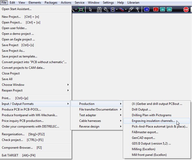
After you had finished your layout/routing work, please use the Menu File / Input/Output Formats / Production / "(X-)Gerber and drill output PCBout", or simply use functional key [F11] or in the layout view press this icon from the toolbar at the top
For the following explanations we use the demo project pic_3d.T3001
The following dialog opens:
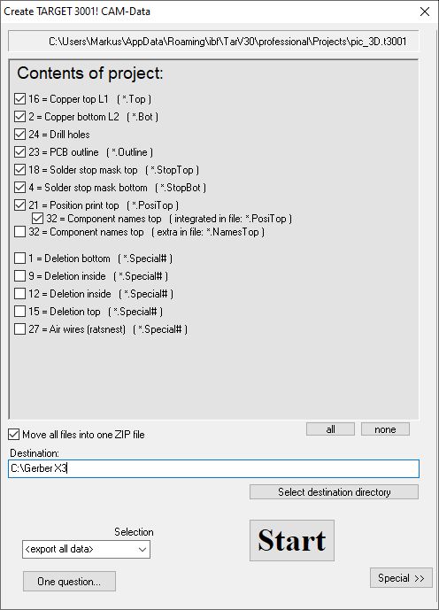
Image: The Create TARGET 3001! CAM-Data dialog
The list shows the Gerber files going to be created (see extensions in brackets) which will be sufficient to manufacture your board. The number and kind of Gerber data depend on the complexity of your project. TARGET recognizes it and puts the expected files to this list. The ones of which you tick or untick the boxes will be generated. Choose a destination directory for saving the files. Now press the Start button. That is all.
The XGerber data are generated to the desired directory. That's what they show up for this example:
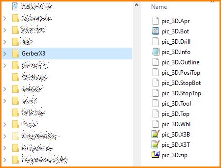
Image: These Gerbers are created from the Pic_3D.T3001 example file
Hand out those files to your PCB manufacturer. The *.zip file provided contains them all. The *.info file can be opened by any text editor and informs your PCB manufacturer in clear words which Gerber files are given regarding this special project. So he can check whether all files had arrived at him. For the project file in our example, the *.info file looks like this:
Image: Contents of the Gerber-Info file based on the project shown
Selection of Gerber data

Image: Data selection when creating Gerbers
The "Selection" option refers to the ability to design multiple sub layouts within one project. You can give this name and output its Gerber data separately. At this point, select the name of the sub-layout whose Gerber data you want to create. Read more about it here: Multiple PCBs within one project
Extension Special
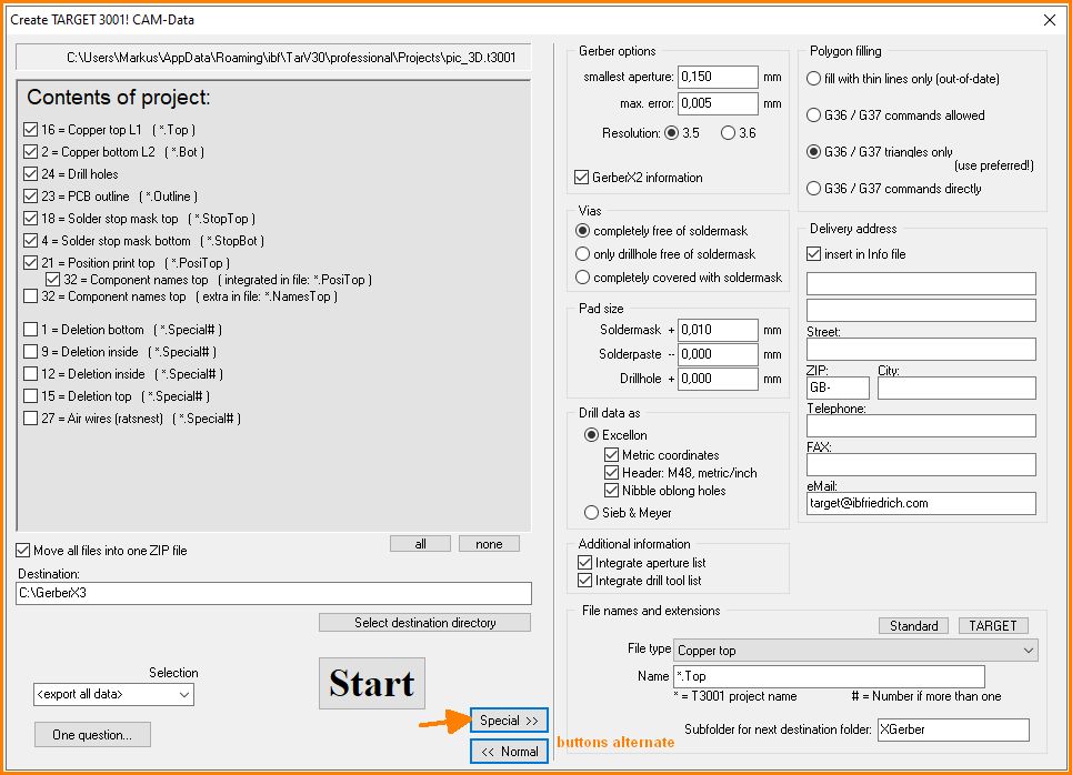
Image: The Create TARGET 3001! CAM-Data dialog opened for Special settings
With button Special>> set further specifications if necessary. If your pcb house should ask Gerber files with different extensions from you please press the Special>> button. This will extend the Gerber dialog and at the bottom to the right give opportunity to choose different extensions (button "Standard").
Follow the link for detailed information.
Important technical note for PCB manufacturers
from version 17.4.0.23 the order of the copper layers is numbered from top to bottom:
double sided:
L1 = Top
L2 = Bottom
or
n-times multilayer:
L1 = Top
L2, L3, L4, L5... = inner layers, counted from top to bottom
Ln = Bottom
In earlier versions copper layers were counted from bottom to top.
Sample project
please have a look here:
Sample Gerber files of a sample project
Gerber X2

TARGET can automatically provide Gerber X2 information: check the box in the Special>> section of the Gerber dialogue.
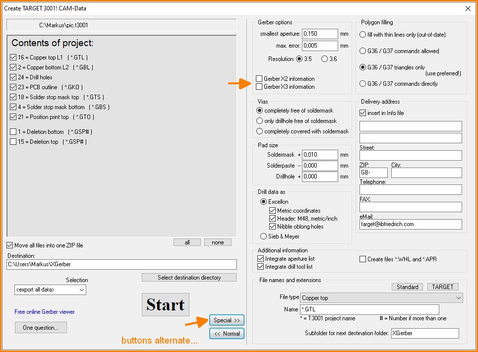
The Gerber files then give information about their content (e.g. copper bottom). All elements "know" which signal and/or component they belong to. This is very useful for e-testing.
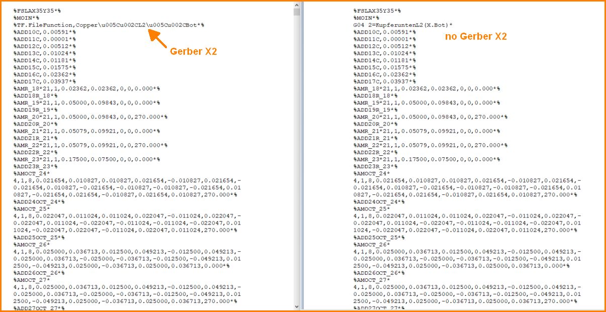
Header information of layer "Copper bottom": With Gerber X2 (left), without Gerber X2 (right).
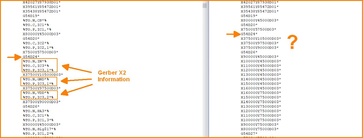
Additional Gerber information: With Gerber X2 (left), without Gerber X2 (right).
Gerber X3

Also the Gerber X3 output feature is on board. Tick the box to have them generated (see diolog at Gerber X2 information). Gerber-X3 data additionally provide information for production, testing, ordering and (automatic) assembly. The Gerber-X3 format is free, open documented and easy to understand. It consists of two additional files *.X3B and *.X3T for assembly Bottom and Top. These are always included to the output. If not needed, ignore!
Component information are those being entered in the symbol change dialogue to the new Order No. button: Distributor and Order Number Double-click on the handle cross of a symbol in the sectoral plan to open the dialogue:
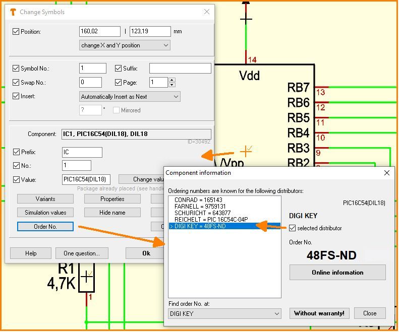
Image: Distributor and order number on file
In the Gerber data both Gerber X3-Files appear.
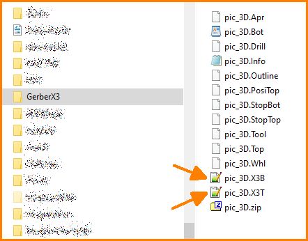
Image: Gerber X3 files
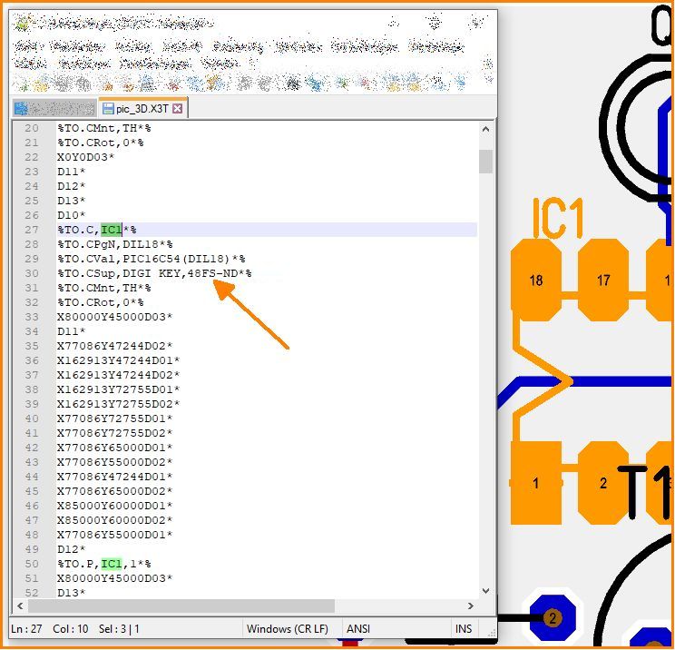
Image: Gerber X3 information related to IC1 being positioned on Top Layer.
Read in of Gerber data to TARGET 3001! (Gerber viewer?)
Please note: TARGET 3001! is not a Gerber viewer! The Gerber import is able to read files containing XGerber (RS-274-X) and Excellon data from various other CAD packages with the aim of importing them layer by layer into a TARGET project.
There is a wide range of excellent Gerber viewers on the web:
Read XGerber and Excellon files
An X-Gerber file is a textfile which may have the following syntax:
%FSLAX23Y23*%
%MOIN*%
%ADD10R,0.053X0.016*%
%ADD11R,0.030X0.030*%
%ADD12R,0.050X0.060*%
%ADD13R,0.049X0.047*%
%ADD14R,0.057X0.022*%
%ADD15C,0.010*%
%ADD16C,0.047*%
G36*
X4135Y3005D02*
X2575D01*
Y3445D01*
X2758D01*
X2759Y3440D01*
X2756Y3439D01*
X2749Y3433D01*
...
An Excellon File (for the drills) also is a text file and for example looks like this:
M48
INCH,LZ
T1F00S00C0.028
T2F00S00C0.035
%
T01
X03325Y0311
X03031Y03115
X02773Y0311
Y03409
...
T02
X03031Y03414
X03325Y03409
...
M30
In case your data look completely different, it's likely that you don't have XGerber or EXCELLON-data.
The opening dialog for Xgerber-import please find in TARGET 3001! Menu File / Input/Output Formats / Data exchange/Documentation / Read XGerber and Excellon files.
An XGerber file-name is overtaken to a line of the dialog and "noted" for conversion...
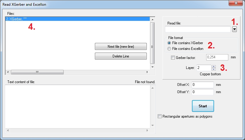
Image: This is the XGerber import dialog!
Button (1.) opens your Windows browser for the selection of one of your given Gerber files which you select from your folder. Now enter which kind of data (2.) the file contains. Afterwards define by (3.), to which layer in TARGET 3001! the data shall be transferred (e. g. layer "2, copper bottom", "24, drillholes"... ). Now see the file already listed in the first dialog line (4.). Now click on "New line". TARGET 3001! now is ready for reception of a new file to a new line (=layer) and you start with 1. again to pick the next data file.
EXCELLON data (most often used to define drill holes) you import the same way.
If you click button: "File contains Excellon" in the box "File format", you'll get the option "Excellon Factor". So you can take influence on the drill data. How big the factor needs to be set is a question of trial and error. The same with "Gerber factor" if you had ticked the XGerber file format. Press "Start" to convert the selected files.
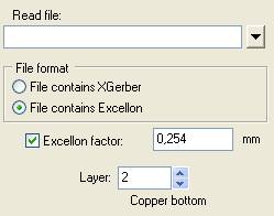
If your Excellon-File doesn't give Information on the diameters of the drilling tools, but you know the diameters, you can simply precede the Excellon syntax with a simple text:
M71
T1C0.6
T2C0.8
...
T17C3.2
G90
M72
T1
X00224Y03282
X00324Y03282
X00424Y03282
X00424Y03487
...
M71 switches over to "mm".
A "T" is followed by the number of the tool e.g. 1...17. After the "C" please find the tool diameter in mm. The dot separates the decimals. The initial file started with "G90" . M72 switches back to imperial unit (inch), which is the standard setting in EXCELLON.
Import multiple files simultaneously
As of V33: When importing Gerber and Excellon projects from other sources, all project layers from the different files can now be read in at the same time. TARGET tries to recognize which layer is in which file by the file extensions. A ZIP file containing several XGerber and Excellon files can also be selected. TARGET assigns suitable layers to the Gerber files according to an experience-based scheme and can also recognize and assign drill files.
Optimization after import
When importing multiple copper layers and the drill holes, all graphic elements become their own "solder pads". For example, a plated-through solder pad becomes an SMD solder pad on top and one on the bottom and a mounting hole. Also an element for the solder resist on top and the solder resist on the bottom is created. This makes 5 "solder pads" which are actually together only one real solder pad.
With SMD pads it is the same. It results in the SMD pad on the copper and in the solder resist and solder paste. That makes three instead of one.
Often rectangular solder pads also come in as two smaller rectangular solder pads and an additional 4 discs in the corners that represent the roundings.
TARGET as of V32 recognizes these constellations and optimizes them:
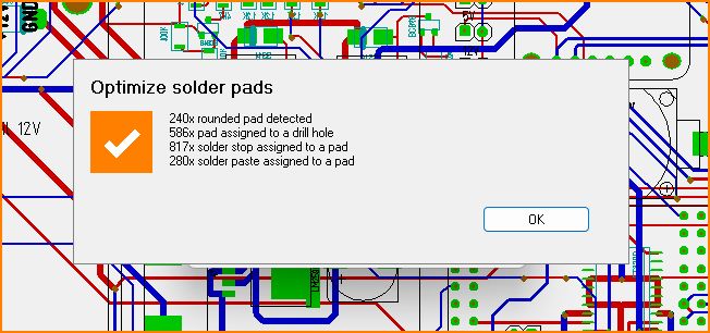
Soldering point optimization
After the XGerber import the optimization is called automatically. You can also call the menu item manually: "File / Input-Output Formats / Data exchange / Gerber and Excellon import / Combine solder pads and drill holes"
Problems with the import of X-Gerber
Please have a look here:
Problems with the import of X-Gerber
Read Gerber (RS274D) and Excellon files using the TARGET 3001! "XGerber import" dialog (recommended)
XGerber (RS274X) carries all aperture information in its genuine layout file. In case you are using the older standard Gerber files (RS274D) for reading in, you must have (identify) the aperture file delivered and need to have it interpreted by TARGET 3001!. Those aperture files do not have a standardized structure at all. Neither the file extensions nor the information within the file itself. Fortunately at least all files (Gerber-, aperture, drill- and drill tool files) are bare text files easily to be read by normal text editors. First open the import dialog in Menu File/Input-/Output formats/Data exchange/documentation/Read XGerber and Excellon files...
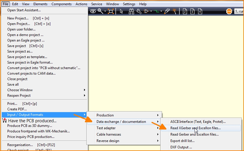
Image: Importing Gerber data using the XGerber import
Now you read in each of your images line by line to a separate layer. Define which file you want to read in first and say to which layer in TARGET you want to import it. The answer to the question which of your file contains which information needs some experience and some testing. Sometimes there is a descriptive info-file. Copper top often is denoted by TOP or T within the file name, copper bottom often is denoted by BOT or B.

Image: Same dialog as above.
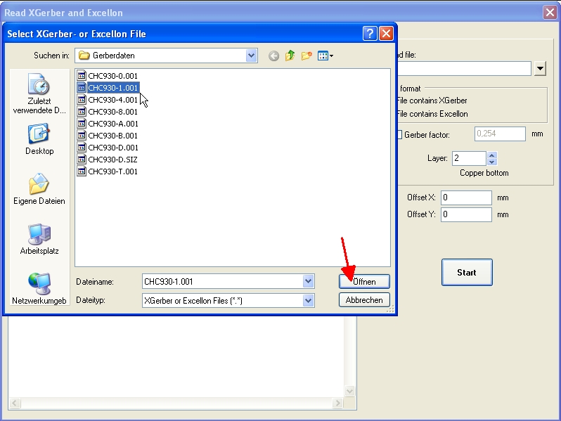
Search for your Gerber data within your directories ("Read file", top right). In this example we choose/destinate layer 2, copper bottom.
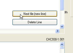
We do the same with the next file...
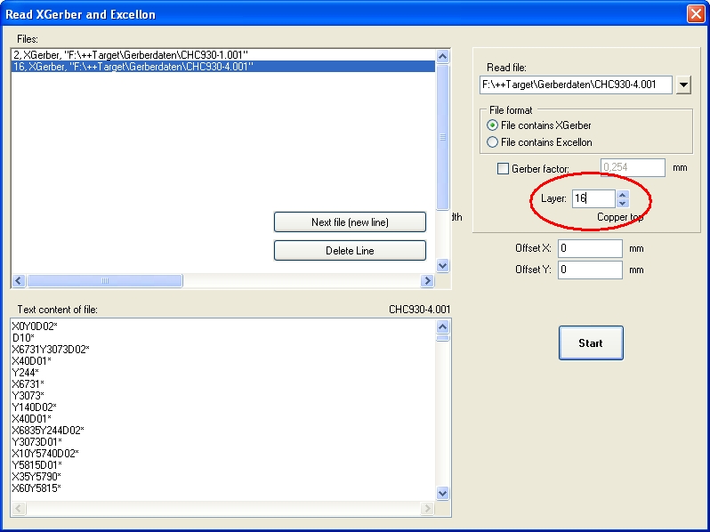
...which contains data for copper top. Import it to layer 16, Copper top.
If you press the START button, you get asked whether you want to search for an aperture file which defines the so called "D codes" because at this time D codes are not sufficiently defined yet. D codes care for size and shape of the apertures which get moved in front of exposure to light. Gerber data control those moves. The aperture file is a kind of description of the exposure tools while Gerber files say what is to be done with them.
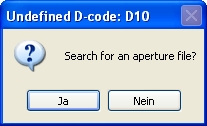
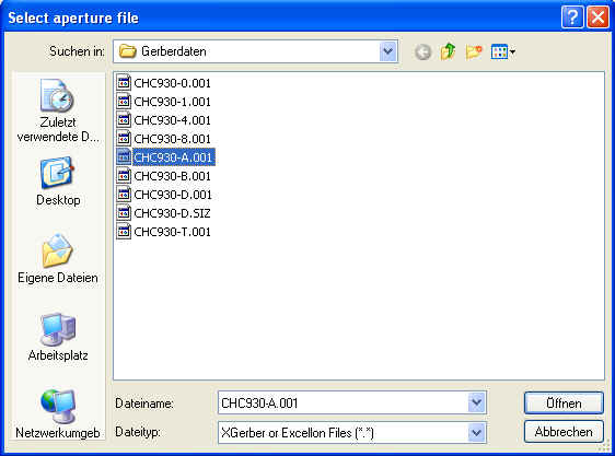
Press button "Yes" and search and select from your file set the one which keeps the aperture information.
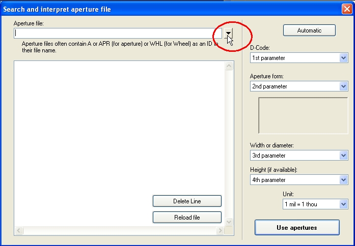
Aperture files often can be identified by an A or APR (aperture) or WHL (Wheel=aperture wheel) in the file name.
After you have selected an appropriate file a dialog opens allowing the interpretation of the aperture data. Aperture data often consist of a header and eventually of an appendix. Both can be deleted. Only those lines are of interest which contain D codes D10,D11,D12...
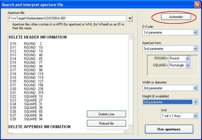
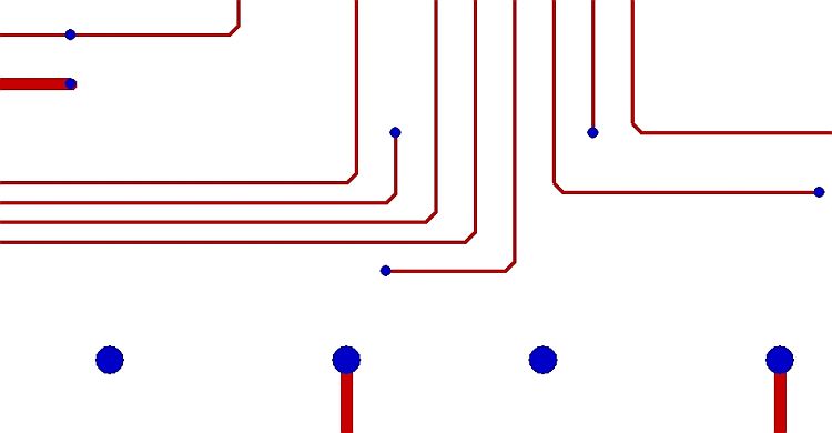
The structure of D codes is not defined. The image only shows an example. Look at a D code line and now interpret it column by column. The button Automatic helps finding a preselection. In our example the first parameter defines the d code, the second the shape of the aperture (ROUND or SQUARE), the third parameter defines width and diameter of an aperture. Because we don't have a fourth parameter "Height"we set it "3. Parameter" too. In which scale your your gerbers come across please set in the last box. If the sequence of your parameters match, please press button "Use apertures". Now see your copper bottom and copper top layout in TARGET 3001!.
Read Gerber (RS274D) and Excellon files using the "Gerber import" dialog (outdated but still working)
Using this tool (File/Input/Output Formats/File transfer/Documentations/Read Gerber and Excellon files) you can view the Gerber (RS274D) data of your project before producing a PCB. The Gerber data are directly read into a TARGET project. By selecting the PCB layers set visible, the corresponding views can be seen and checked with the TARGET project in separated windows besides each other. Additionally you can import Gerber data from other layout CAD packages and edit those within TARGET.
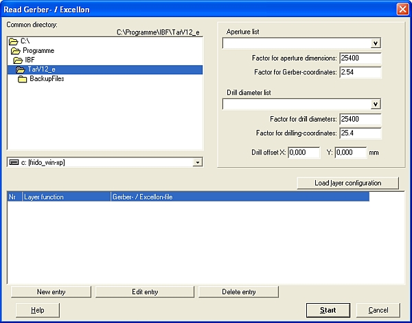
- Open a new project "PCB without schematic"
- Click on "Read Gerber & Excellon files" in menu File/Input/Output Formats/File transfer/Documentations/...
- Choose your standard directory which contains the Gerber data desired
- Choose the corresponding aperture and drilling list
- Click on "load layer configuration", if you want to use the existing layer configurations of the TARGET directory, or if you already edited an individual configuration. Here you have the opportunity to open "Gerber configurations" (edited by the Gerber Out function) or "GerberIn Configurations" (edited by "GerberIn")
- Now the dialog opens "Load Configuration". You may enter a new name for the configuration files. Those are saved in ASCII format
- All TARGET supplied configuration files have stars in their file names (e.g. *.BOT for copper bottom). Thus enter an expressive file name regarding to your Gerber file.
- If you cannot use one of the proposed configurations, edit a new one on your own. Drop information which layer (e.g. copper bottom) is to be found in which file (e.g. TESTFILE.BOT)
- Click on New Entry, for to define further layers, e.g. drill_file *.DRL
- If all settings are made, enter "START"
REMARK: Gerber data concerning the layer "solder stop" should be read in from another layer than "Solder Stop Bottom", because TARGET recognizes the pads of the Solder Stop Layer automatically by activating them in the normal layer dialog. Gerber data of the solder stop layer with topping of the vias are ignored then or dominated by those "recognized".
If the external CAD format you need concerning the aperture and drilling list not is offered by TARGET, please describe it to us (evtl. using an example - file). We add all formats you drop to us into the list as we estimate it reasonable.
What's the difference between Gerber and G-Code?
G-Code and Gerber are similar but describe different things: Gerber describes the drawing of a PCB layer. A command in Gerber mostly results in a piece of a track or in a pad. G-Code mostly is used for controlling milling machines. A command in G-Code normally results in a movement of the milling bit.
Regarding isolation milling, moving the milling tool inside tracks and pads would destroy them. The movement has to be outside along the tracks and pads to create isolation channels all around. TARGET 3001! is able to compute the G-Code for PCBs, regarding the milling bit diameter and the track widths. Because TARGET 3001! can also import Gerber files, it can be used as a universal Gerber-to-G-Code converter.
G-Code can be created in TARGET 3001! by the menu option:
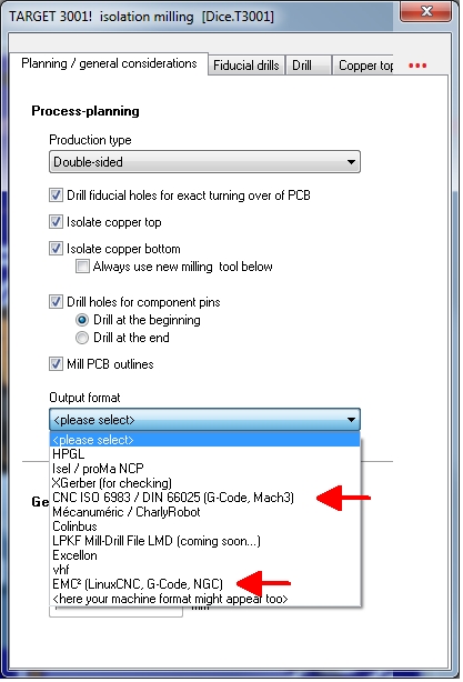
This menu entry opens the following dialog where you can opt for G-code as output format.
