Engraving insulation channels
Isolation milling
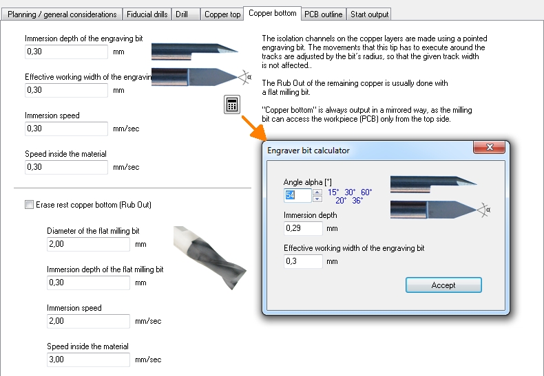
See menu: File / Input/Output Formats / Production / "Engraving Insulation Channels". The required insulation between tracks is made by engraving insolation channels. So the trick is not to mill the tracks away but mill away all the surrounding copper (at least the aura of each signal). TARGET 3001! calculates the outline of the tracks and gives them out in different formats:
 |
*.plt (HPGL) |
The mentioned outline- and engraving data can be used by CNC-machines in order to manufacture sample- or small series of your PCB. Please use the remarks in the following dialogs as explanations.
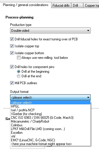
Planning/General considerations
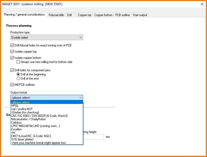
Image: Various milling formats are supported...
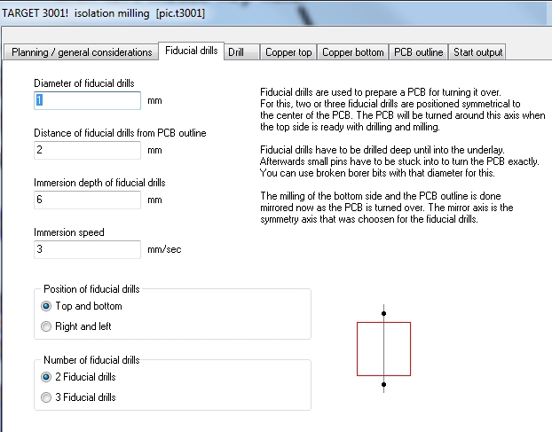
Fiducial drills
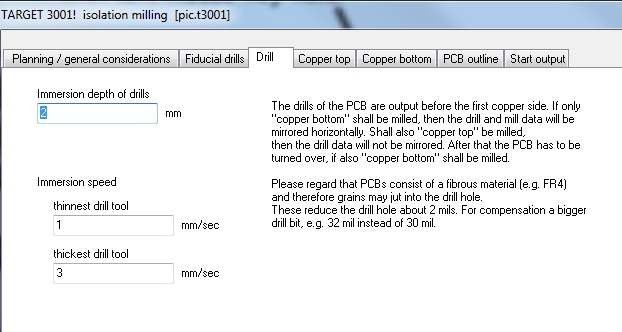
Drill
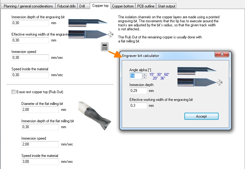
Copper top
Copper bottom
PCB outline
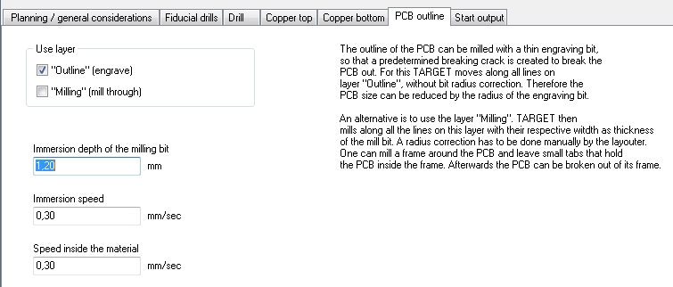
Tick the box "Outline" (engrave):
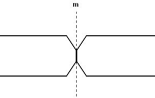
The outline of the PCB either is cut with a sword milling bit or carved with a engraver bit (V-cut). By this means a predetermined v-groove will result from which you can break overshooting material. All lines you have drawn on layer 23, Outline, get cut exactly in the middle, i. e. without a diameter correction. Thus the board outline decreases by the radius of the tool.
Tick the box "Mill" (mill completely):
Alternatively layer "25=Milling" can be used. It's neccessary to draw an extra outline upon layer 25. Your milling machine will move exactly according to the middle of these lines. It will use half the width of the line as an advice for the diameter of the corresponding milling tool. A radius correction needs to be done manually by the layouter. E.g. if you want to mill with a 3mm milling tool around your layout you need to draw a 3mm line accordingly upon layer 25=Milling. The radius correction needed (stay 1.5mm out of the cutting edge) you need to recognize in your drawing yourself.
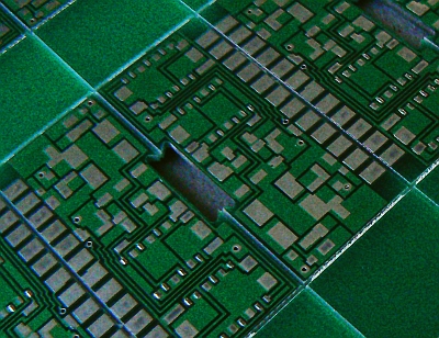
For starting a line press key [Ctrl] + [2] in the layout view. Press key [o] for options to set layer 25 and the width of it. Now drag the line by M1. You can let the board be milled out completely or leave narrow tabs for breaking it out from the remaining "frame" later (see image above).
In TARGET V30 there is an elegant tool to have space and ligaments (bars) in a panel be designed automatically. Please have a look at article "Panel".
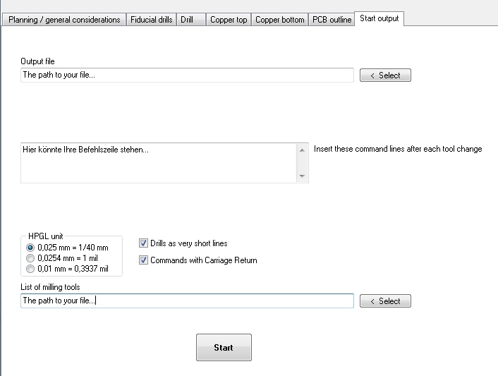
Start output
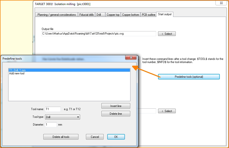
Predefine tool list according to tool magazine
The following tool types can appear in the info file for milling cutters:
Fiducial = Fiducial drills outside the outline of the board
Drill = Drilling
Mill = Board outline. Can be a cutter or a cylinder bit
Isolate = Cutter bit for isolation milling
Isolate2 = evtl. identic cutter for isolation milling (meant for bottom side use to force a Halt for flipping the board)
Rubout = cylindric bit for rubbing out
Flip = tool forcing a Halt to flip the board
Tool change
Before a tool change, the machine moves to hover height and then to the center of the workpiece.
The following HPGL-commands are used when engraving insulation channels
IN = Initialize
SP = Select Pen to change the tool automatically or manually or evtl. to Flip PCB for reverse treatment
PA = Plot Absolute
PD = Pen Down
PU = Pen Up
Milling text into the copper
A user asks:
I want to have the letters "GND" milled into my ground plane. How to do so?
Solution:
You need to place the text directly into the copper layer, e. g. Layer 16, Copper top. Use font "DinIsoAnsi".
Customer feedback:
That's it!
You see the the text in the layout only if groundplane (Layer 0) is faded out, but it mills perfectly. Thank you!
Mill a logo made of lines into the copper
say on copper top you would like to have a logo made of lines being embedded into the ground. This logo shall not be cropped (in the sense of leaving the line embossed) but the line itself directly shall be milled away. Either you draw the logo with lines using the drawing functions or you may import a vector graphics eg. in format *.dxf.
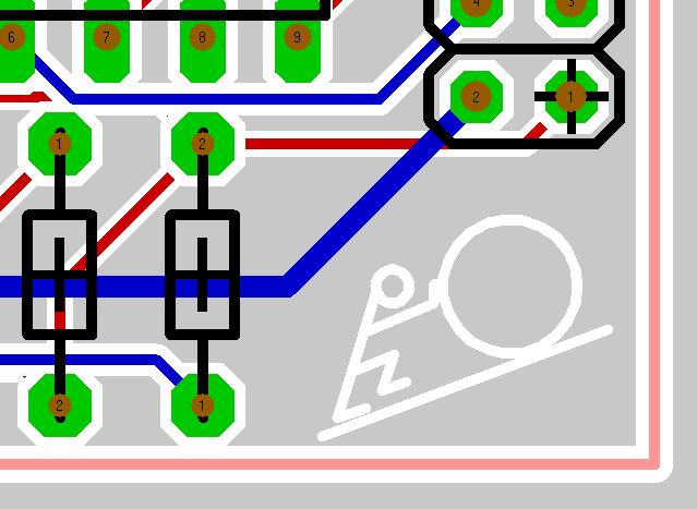
Image 1: A little stickman, drawn on layer 15, Deletion top.
If you have imported an image, you need to shift it to layer 15. Highlight it completely and press keyboard key [e] for edit. The following dialog opens.
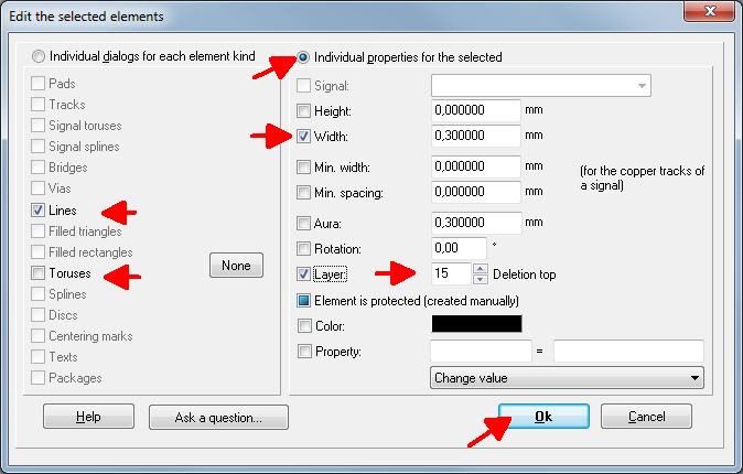
Image 2: To the left only tick "Lines". To the right choose a line width of 0,3mm and select layer 15, Deletion top.
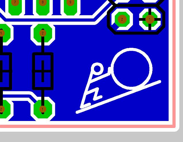
Image 3: After you have created the ground plane the above image shows up
Now save the project and create the isolation milling data.
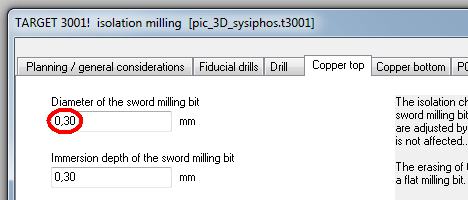
Image 4:The isolation milling dialog
Choose in the isolation milling dialog a width of the tool which is smaller or equal 0,3mm (the line width of your logo). In the same dialog (Image 4) in TAB Planning/General considerations you might create the format: "XGerber (for checking)". In the Gerber Viewer (GCPrevue) you now can check the movements of the milling tool.
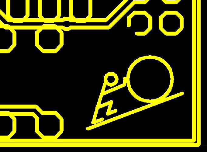
Image 5: The layout in GC prevue
Important: The width of the deletion lines at least must be equal or even bigger than the diameter of the milling bit. Otherwise they will be ignored unfortunately.
An example with images
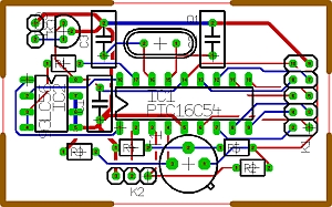
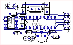
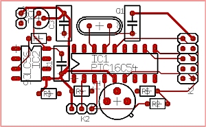
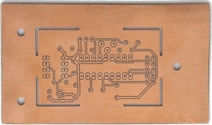
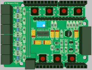
| A TARGET 3001! layout:
|
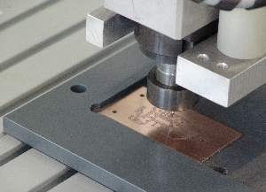
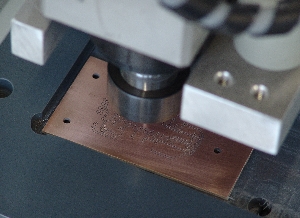
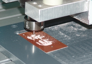
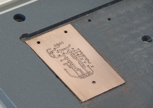
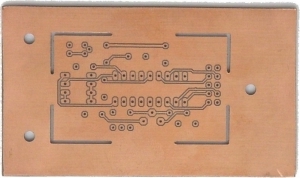
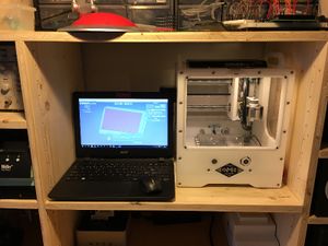
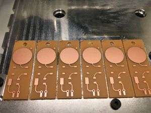
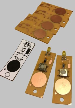
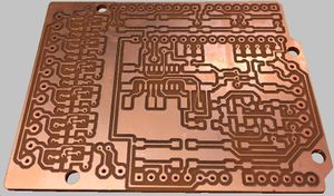
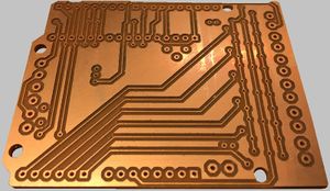
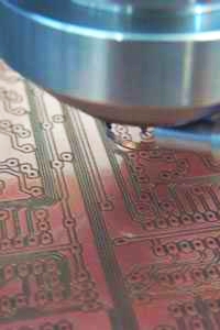
Our highly esteemed customer Mr. Nietlispach works with a Othermachine milling machine. Mr. Nietlispach presents the following images to us as example and recommendation. (Many thanks to Mr. Nietlispach):
|


