DXF
General
DXF (Drawing Interchange Format) is a data exchange format between different CAD programs of Autodesk Inc. Open it in menu File / Input/Output Formats / File transfer/Documentation / ...
TARGET 3001! saves all details of your schematic and PCB with an internal data structure. The DXF format gives opportunity to make those data being viewed and handled by other CAD programs.
DXF is defined that way that even complicated matters of any programs in any programming language can be generated. The program needs to fulfill two conditions:
- It must be able to read an ASCII-file
- It must be able to load and process numbers as pairs out of this file
Unfortunately the data transfer with DXF is problematic. This refers to the different qualities of different DXF converters:
- There is no DXF standard. The format has developed organically and still is developing.
- As far as we know DXF is not sufficiently described.
- Autodesk themselves offer the following specifications: http://usa.autodesk.com/adsk/servlet/item?siteID=123112&id=8446698
(If you know other useful DXF documentation we would be happy if you would let us know.) - In practice the format is not unitary. The DXF-Import in many other programs does not use the AutoCAD-reference. Some headers often interdict an import.
- All coordinate- and length values of a DXF file are not showing units.
- The measurement system of a drawing (Millimeter, Inch, ...) is not part of the drawing information itself.
- DXF is suitable very well for the definition of lines but suitable badly for the definition of filled shapes.
In order to export to DXF please use in AutoCAD or any other CAD construction software package the commands Explode esp. Origin. This will make the image "flat" so that TARGET can read it.
Import a DXF-File
Maybe you wish to import parts of the schematic or parts of the layout from a DXF file to TARGET.
- Open TARGET 3001! and choose the PCB view if you want to import a DXF-file as part of a PCB layout.
- Open TARGET 3001! and choose the schematic view if you want to import a DXF-file as part of a schematic.
Now choose in TARGET 3001! main menu File / Input/Output-Formats / File transfer/Documentation / "DXF Import".
Now from the Windows file browser select the *.dxf file you wish to import. Click "Open".
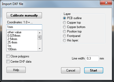
Image: The dialog: "Import DXF file"
Close Polygons: Sometimes polylines have the shape of a polygon, but are still open at one point. Box ticked will cause the start and end point of a polyline to be linked by a line. The polygon is closed.
Center DXF data: A DXF file in TARGET will be displayed in the first quadrant of the coordinate system (=where the X and Y values are positive). Objects with a size of 60 x 60 cm can be mapped here. If the object is larger, its center will be placed placed on the origin of the coordinate system. In consequence coordinates of points of the object can achieve negative values. No problem - the drawing will be mapped on all 4 quadrants of the coordinate system. Box ticked means: No matter how big the object is, its center will be placed to the origin in any way. To define its center, put an imaginary square over the complete drawing. Now connect its corners by diagonally arranged lines. Center is, where both lines intersect.
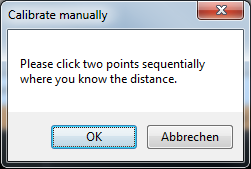
In this dialog please do the scaling settings. Define the layer to which you like to import your file. Sometimes you are insecure in respect to the dimensioning of the DXF file to come. Which scaling factor is correct? Using this button, you can ![]()
Maybe you know the diameter of a drilling or the length of a certain line of the drawing which you like to import. Now you hover the mouse to a point in question and click the mouse. Do the same with the second point of the object.
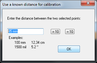
In the opening dialog enter the absolute value for the length of the distance highlighted e. g. 85 mm. Now press "Start" in order to activate the import process. TARGET knows now how to determine the dimensions of the DXF file, in order to display it correctly.
Export of a DXF-file
Save your project in "TARGET 3001!". Open the DXF driver in TARGET 3001! menu File / Input/Output Formats / File transfer/Documentations / DXF Output. What you get is the following dialog. Enter a name at Output (DXF) otherwise the existing project name is overtaken. Choose the destination of the dxf-file to be generated by the button ![]()
Now select from the registers for several alternatives.
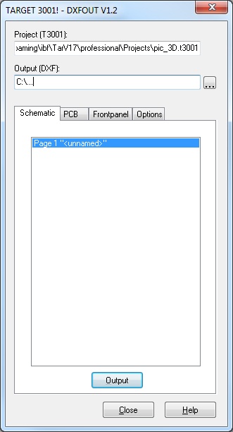
Image:Select the desired schematic page in the "Schematic" TAB. In this example project there is only one schematic page.
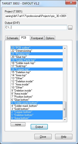
Image: Use the PCB-tab in order to select the layers you'd like to have exported to DXF.
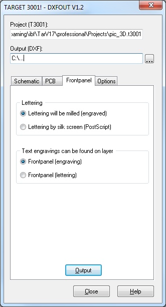
Image: The Frontpanel tab.
.
The contents of the layer "Front panel (contours)" is going to be exported. In addition you can define whether letterings are images or engravings and if engraved on which layer in TARGET the engraving commands can be found. NOTE: For engraving of lettering it is best practise to use font made of a line like the font "TARGET" or "Din ISO Ansi". These fonts the character is drawn in single action without lifting the tool. Windows fonts eventually need several tools and movements per character.
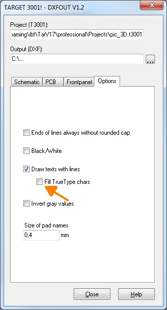
Image: If you are unsure in the Options tab, please leave the boxes unticked (default settings are used).
Some laser machines expect True Type font, i.e. vectorized contours which either get filled by the laser machine or which are filled already. From Version 17 there is opportunity to define such True Type fonts as "filled".
Now export your file in DXF format by pressing "Output" in one of the first three tabs.
Watch your DXF File for example in "Free DWG Viewer" or in "Mini CAD Viewer" or in any other DXF-Viewer. The two mentioned ones are free.
.


